
Installation Guide


AutoDome 100 Series Fixed Camera Installing Roof Parapet and Pipe Mounts | en 47
Bosch Security Systems, Inc. Installation Manual F.01U.217.818 | 1.0 | 2011.04
3.7.1 Wiring for Multiple AutoDomes
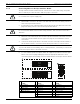
To wire multiple AutoDomes in a series, or “daisy chaining,” you must apply a terminating
resistor to the last dome of the series. The Interface Board is supplied with a 100 Ω
terminating resistor located between the Biphase terminals C- and C+ (pins 1 and 2) of the
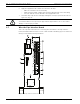
P105 control connector (see item 5 in Figure 3.10 above). Remove the resistor from all but the
last AutoDome Interface Board. The maximum number of AutoDomes that can be daisy
chained is four (4).
If using the RS485 protocol for control, switch the terminating resistor from the Biphase C+
and C- terminals to the RxD+ and TxD- terminals (pins 4 and 5) of the P105 control connector
for the last dome (refer to item 6 in Figure 3.10 above).
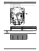
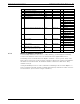
Ref. Description Connector Wire Gauge Pin Description
1 Pipe Interface Module
2 Video Coax In J102
3 6-pin Connector Alarms In (3-7) P103
4 4-pin Connector Alarms Out (1-3) P102
5 100 Ω Resistor P105
6 Data In/Out P105 AWG 26-16 1 Biphase (C-)
2 Biphase (C+)
3 Earth Ground
4RxD +
5 TxD -
6Signal Ground
7 Alarms In (EOLR Supervised, 1-2) P104 AWG 26-16 7 Ground
6 Alarm 2
5 Alarm 1
4 Earth Ground
8 Relay Output P104 AWG 26-16 3 Normally Closed
2 Common
1 Normally Open
9 Dome Power P101 AWG 18-14 3 Dome 24 VAC
2 Earth Ground
1Dome 24 VAC
10 Heater Power P107 AWG 18-14 2 Heater 24 VAC
1 Heater 24 VAC
11 RJ45 Ethernet or UTP Video
(Ethernet for VG5 700 Series only)
J101
12 To AutoDome