
Installation Guide


30 en | Installing the Pendant Arm Wall, Corner, and Mast (Pole) Mounts AutoDome 100 Series Fixed Camera
F.01U.217.818 | 1.0 | 2011.04 Installation Manual Bosch Security Systems, Inc.
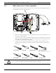
11. If using UTP for video, connect the incoming RJ45 video connector, installed previously,
to the UTP Video/Ethernet cable (cable 5). Refer to Section 5 Cable and Wire Standards,
page 61, for detailed wire and connection information.
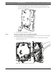
12. Connect the outgoing alarm wires to the flying leads coming from the 4-pin Alarm
Outputs cable (cable 6).
13. Connect the incoming alarms wires to the flying leads coming from the 6-pin Alarm Inputs
cable (cable 7).
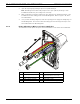
14. Connect the incoming serial communication wires to the 6-pin mating connector supplied
with the VG4-A-ARMPLATE kit. Ensure that the 100 Ω resistor remains connected to the
Biphase C- and the Biphase C+ terminals. Remove the resistor only in the following cases:
– If the AutoDome is not the last AutoDome in a daisy chain.
– If the Biphase C- and the Biphase C+ terminals receive a line input audio signal.
Refer to Section 5 Cable and Wire Standards, page 61, for detailed wire and connection
information.
15. Attach the 6-pin serial communication mating connector to the Serial Communication
(cable 8) cable.
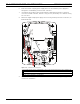
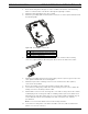
16. Connect the Earth ground wire, if available, to the crimp ring terminal inside the
Mounting Plate. Refer to Figure 2.14 above.
Note: The Earth ground is not provided with the VG4-A-ARMPLATE kit; it is a ground
connection made at the installed location.
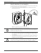
17. After making the harness connections to the Mounting Plate, rotate the Pendant Arm to
close and tighten the two (2) captive screws to 10-12 N-m (90-105 in.-lbs).
NOTICE! After all wiring is complete, close the cover door and tighten the two (2) captive
screws on the cover door to 10-12 N-m (90-105 in.-lbs).