
Installation Guide


24 en | Installing the Pendant Arm Wall, Corner, and Mast (Pole) Mounts AutoDome 100 Series Fixed Camera
F.01U.217.818 | 1.0 | 2011.04 Installation Manual Bosch Security Systems, Inc.
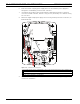
2.7 Make Connections in Power Supply Box
Refer to Table 2.2, Page 21 to locate the various connectors in the power supply box and make
the following connections detailed below.
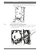
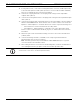
Figure 2.10 Pendant Arm connections to Power Supply Box
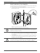
1. Attach the earth ground wire (item 1 in the illustration above) to the grounding screw on
the left side of the power box.
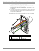
2. Connect the 6-pin Control In/Out Plug, installed previously, to its mating connector P106
in the power box. If this product is a Fiber Optic model this step is not required, since all
control data is sent through the fiber cable.
3. Connect the 6-pin Control to Dome Plug from the Pendant Connector Harness to its
matting connector P105 in the power box. (For Fiber Optic model connect to the P106
connector.)
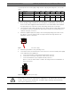
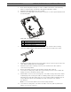
Control Data Coax Video 24 VAC Power UTP Video/Ethernet
(Ethernet for VG5 700 Series only)
Alarm Inputs Alarm Outputs Relays Grounding Strap
1 2 3
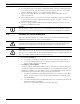
WARNING!
Do not connect the RJ45 connector unless using UTP video or Ethernet.