
Installation Guide


18 en | Installing the Pendant Arm Wall, Corner, and Mast (Pole) Mounts AutoDome 100 Series Fixed Camera
F.01U.217.818 | 1.0 | 2011.04 Installation Manual Bosch Security Systems, Inc.
6. Attach a BNC connector to the incoming video coax cable. If using UTP for video attach
an RJ45 plug to the incoming UTP cable. If installing a Fiber Optic model, attach an ST
fiber plug to the optic fiber cable. Refer to Section 5 Cable and Wire Standards, page 61,
for the different methods of transmitting video and control protocols, and wire
specifications.
Note: Do not connect the RJ45 connector unless using UTP video.
7. Attach a BNC connector to the incoming video coax cable. If using UTP for video attach
an RJ45 plug to the incoming UTP cable. If installing a Fiber Optic model, attach an ST
fiber plug to the optic fiber cable. Refer to Section 5 Cable and Wire Standards, page 61,
for the different methods of transmitting video and control protocols, and wire
specifications.
Note: Do not connect the RJ45 connector unless using UTP video.
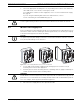
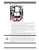
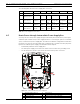
8. If you are connecting alarm inputs and outputs, attach the supplied 4- and 6-pin Alarm
Connectors with flying lead wires to the appropriate incoming alarm wires.
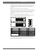
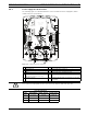
Figure 2.3 Alarm and relay connectors
9. If you are connecting supervised alarms and relays, attach the supplied 7-pin Relay
Connector to the appropriate incoming wires. Refer to Figure 2.3, Page 18, above, for the
wire connections. Refer to Section 6 Alarms and Relay Connections, page 69 for more
details about wiring alarms and relays.
1 4-pin Alarm Connector
(P102)
2 6-pin Alarm In Connector
(P103)
3 7-pin Relay Connector
(P104)
Pin Description Pin Description Pin Description
1 Alarm Out 1 1 Alarm In 3 1 Normally Open
2 Alarm Out 2 2 Alarm In 4 2 COM
3 Alarm Out 3‡ 3 Alarm In 5 3 Normally Closed
4 Alarm Ground 4 Alarm In 6 4 Earth Ground
5 Alarm In 7 5 Analog Alarm 1
6 Alarm Ground 6 Analog Alarm 2
7Ground
1
1
2
3
4
5
6
2
3
4
N.O. COM N.C. A1 GND A2
1
PIN
PIN
P102
P103
P104
WHITE
ORANGE
BROWN
GREEN
WHITE
ORANGE
BROWN
GREEN
YELLOW
BLUE
2
3
4
5
6
7