Thermostat Installation Manual Series tTSTBM3H2CPH6W-A thermostat and Wireless Communicating Base Module TSTBM3H2CPH6W-A 6 720 220 376 Revised 02-13
of Contents 2 Table TSTBM3H2CPH6W-A Table of Contents Thermostat Applications Guide.............................................................................. 3 Power Type............................................................................................................. 3 Thermostat Quick Reference.................................................................................. 3 Installation Tips................................................................................................
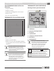
TSTBM3H2CPH6W-A Thermostat Quick Reference The TSTBM3H2CPH6W-A offers the following: • 3 stages of heating 3 THERMOSTAT QUICK REFERENCE Getting to know your thermostat • 2 stages of cooling 2 • Temperature averaging with remote sensors • Wireless control 5 • 5+1+1 & 7 Day Programmable 1 Thermostat Applications Guide Description Gas or Oil Heat Yes Electric Furnace Yes Heat Pump (No Aux. or Emergency Heat) Yes Heat Pump (with Aux.
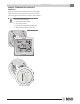
Installation TSTBM3H2CPH6W-A Tips Days of the week and time. Flashes ambient humidity level. May also flash outside temperature when used with TSTBM-OTS--TW-A. OUTDOOR will show. Programmable Time Period Icons: This thermostat has 4 programmable time periods per day. HOLD is displayed when thermostat program is permanently overridden. Displays the user selectable setpoint temperature. System operation indicators: Temperature: Indicates the current system temperature.
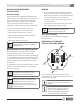
n n TSTBM3H2CPH6W-A Base Module—Basement Installation Installation Base Module—Basement Installation 5 Wiring Wireless Range Range between the TSTBM3H2CPH6W-A and the base module is up to 100 feet with no obstructions and up to 50 feet in standard residential metal, brick, and concrete construction. To extend the range try placing the base unit higher if in a basement or further away from large metal objects. 1.
Thermostat TSTBM3H2CPH6W-A Installation and Wiring The base module must be hardwired (C and R terminals connected to 24V power). n Thermostat Installation and wiring Caution UP Caution C Battery installation is optional if there are no remotes connected to the Master Thermostat (C terminal connected). If you connect an outdoor remote and/or indoor remote sensors it is required the thermostat be hardwired.
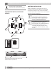
on Mount Thermostat And Base Module TSTBM3H2CPH6W-A Mount Thermostat and Base Module Align the 4 tabs on the subbase with corresponding slots on the back of the thermostat or base module. Then push gently until the thermostat or base module. To insure a solid fit between the thermostat and the subbase: 1. Mount subbase to a flat wall 2. Use screws provided 3. Drywall anchors should be flush with the wall 4.
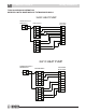
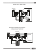
TSTBM3H2CPH6W-A Wiring Schematics TYPICAL WIRING SCHEMATICS WIRELESS WITH BASE MODULE TSTBM3H2CPH6W-A 3H/2C HEAT PUMP TSTBM3H2CPH6W-A THERMOSTAT C R PACKAGED HEAT PUMP BASE MODULE RH R RC G G Y1 Y1 Y2 Y2 C D O B C W1 O W2/E B W1/E W2 H 2H/1C HEAT PUMP TSTBM3H2CPH6W-A THERMOSTAT C R BASE MODULE PACKAGED HEAT PUMP RH R RC G G Y1 Y1 Y2 Y2 C D O B C W1 O W2/E B W1/E W2 H 6 720 220 376 Subject to change without prior notice Revised 02-13
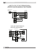
Wiring Schematics TSTBM3H2CPH6W-A 3H/2C SPLIT HEAT PUMP FAN COIL / AIR HANDLER COMPRESSOR SECTION BASE MODULE R RH R G RC Y1 Y1 G Y2 Y2 Y1 C C Y2 O W1 D B W2/E C O TSTBM3H2CPH6W-A THERMOSTAT B C W1/E R W2 H 3H/2C HEAT PUMP WITH GAS/OIL FURNACE HEAT BACKUP FAN COIL / FURNACE BASE MODULE R RH R G RC Y1 Y/Y1 G Y2 COMPRESSOR SECTION Y2 Y1 C C Y2 O W/W1 D B C C TSTBM3H2CPH6W-A THERMOSTAT R O B W1/E W2 H Revised 02-13 Subject to change without prior notice
TSTBM3H2CPH6W-A Wiring Schematics JUMP "E" & "W2" AT THE TSTBM3H2CPH6W-A THERMOSTAT WHEN THE HEAT PUMP EQUIPMENT DOES NOT HAVE AN EMERGENCY HEAT TERMINAL TSTBM3H2CPH6W-A THERMOSTAT C PACKAGED HEAT PUMP BASE MODULE R RH R RC G G Y1 Y1 Y2 Y2 C D O C W B O B W1/E W2 H 2H/2C AIR CONDITIONING W/ ELECTRIC HEAT BACKUP FAN COIL / AIR HANDLER BASE MODULE COMPRESSOR SECTION R RH R G RC Y1 Y1 G Y2 Y2 Y1 C C Y2 W1 D W2 C O B TSTBM3H2CPH6W-A THERMOSTAT C W/E R W2 H 6 720 2
Wiring Schematics TSTBM3H2CPH6W-A UNIT WITH ACTIVE OR PASSIVE DEHUMIDIFICATION AND HUMIDIFICATION RELAY COMMON FROM HVAC EQUIPMENT HVAC EQUIPMENT PASSIVE / ACTIVE DEHUMIDIFICATION BASE MODULE RH RC G Y1 Y2 D C HUMIDIFIER EQUIPMENT HUMIDIFIER SOLENOID O B W/E W2 H Revised 02-13 Subject to change without prior notice 6 720 220 376 11
TSTBM3H2CPH6W-A Terminal Designations Terminal Designations on Base Module Terminal 2 Heat 2 Cool Conventional System 2 Heat 2 Cool Heat Pump System 3 Heat 2 Cool Heat Pump System RC Transformer power (cooling) Transformer power (cooling) Transformer power (cooling) RH Transformer power (heating) Transformer power (heating) Transformer power (heating) C Transformer common Transformer common Transformer common B Energized in heating (not used) Heat pump changeover valve energized in he
Establishing Communication Links Establishing Communication between TSTBM3H2CPH6W-A Master Thermostat and the Base Module TSTBM3H2CPH6W-A 13 Step 1. LED Relay Indicator Easy, Two Step Communication Link To set up the initial link between the Master Thermostat and the base module please follow these steps: 1. Press and hold the base module button for 3 seconds. The Blue LED will flash when ready to receive initial signal from TSTBM3H2CPH6W-A. (Base module must be powered by 24V.
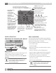
TSTBM3H2CPH6W-A Technician Setup Menu Step 2. Technician Setup Menu Light key This thermostat has a technician setup menu for easy installer configuration. To set up the thermostat for your particular application: 1. Press MENU button 2. Press and hold TECHNICIAN SETUP button for 3 seconds. This 3 second delay is designed so that homeowners do not accidentally access the installer settings. 3. Configure the installer options as desired using the table below.
Technician Setup Menu TSTBM3H2CPH6W-A 15 Tech Setup Steps LCD will show Filter Change Reminder This feature will flash FILT in the display after the elapsed run time to remind the user to change the filter. A setting of OFF will disable this feature. Adjustment Options Factory Default Settings You can adjust the filter change reminder from OFF to 2000 hours of runtime in 50 hour increments.
Technician Setup Menu 16 TSTBM3H2CPH6W-A To lock the keypad, hold down the or keys for 3 seconds. You will see a lock in the display. To unlock the keypad hold down the or keys for 3 seconds. Tech Setup Step (Continued from the previous page) LCD will show Factory Default Settings Adjustment Options Keypad Lockout Keypad lockout allows you to configure the thermostat so that none or some of the keys do not function..
Technician Setup Menu TSTBM3H2CPH6W-A 17 Tech Setup Step (Continued from the previous page) LCD will show Program Options Adjustment Options Factory Default Settings Use the – or + keys to select 7d for 7 day, 5d for 5+1+1, or 0d for nonprogammable. 5d Display Light The display light can be OFF configures display light to come on only with the light key, which will save battery power. ON configures the display light to come on when any key is pressed.
TSTBM3H2CPH6W-A Technician Setup Menu Tech Setup Step (Continued from the previous page) LCD will show Gas Auxiliary for Heat Pump (only available in HP mode) This option will turn the heat pump off 45 seconds after the auxiliary heat relay turns on. For 2 heat applications, the first stage will turn off 45 seconds after the auxiliary stage turns on. For 3 heat applications, the first and second stage will turn off 45 seconds after the auxiliary stage turns on.
Technician Setup Menu TSTBM3H2CPH6W-A 19 Tech Setup Step (Continued from the previous page) LCD will show Adjustment Options Factory Default Settings Remote Sensor Enables the use of up to four indoor sensors TSTBM-RRS-TW-A. Selecting YES requires the TSTBM3H2CPH6W-A master thermostat to be powered with 24V on C and R terminals. NO When NO is selected the thermostat is unable to connect to an indoor remote sensor TSTBMRRS--TW-A.
TSTBM3H2CPH6W-A Technician Setup Menu Balance Point: The system operates differently when a balance point is used on a dual fuel system. The balance point outdoor temperature setting will be the outdoor temperature at which the thermostat chooses either the heat pump or gas furnace. For Example: A balance point setting of 30ºF will turn on only the heat pump above 30ºF and only the gas furnace below 30ºF. Y1 will be stage one above 30ºF and W2 will be stage one below 30ºF.
Technician Setup Menu TSTBM3H2CPH6W-A 21 Tech Setup Step (Continued from the previous page) LCD will show Adjustment Options Factory Default Settings Dehumidify This feature forces the A/C to run longer to remove humidity when with AC Use the – or + keys select YES or NO. If selected YES allows over cooling to be used to control humidity in Cool mode. If NO is selected the system will not use over cooling.
TSTBM3H2CPH6W-A HUM and DHM Terminals UNDERSTANDING SWING AND STAGING Temp Actions All Bosch thermostats have adjustable swings. Cycling your HVAC system is a balance between user comfort and equipment efficiency. Equipment wear and tear is also a consideration.
TSTBM3H2CPH6W-A Setting Target Humidity Setpoint 23 Humidification / Dehumidification Recommendation for Bosch Heat Pump With a residential Bosch Heat Pump, it is recommended to use the cool-to-dehumidify option with the equipment. When a humidity call is made by energizing the “D” terminal, the fan motor will slow down to better dehumidify the air by over cooling. Humidification 1. Select HUM Terminal #1. This will work with Bosch Humidifier Series and replace the manual humidistat.
TSTBM3H2CPH6W-A Setting 5+1+1 Program Recommended Heating Settings: Set 5+1+1 Program Schedule Increasing Humidity To customize your 5+1+1 program schedule, follow these steps: The table below shows recommended indoor humidity levels in relation to outdoor temperatures during heating (adding humidity). Weekday: 1. Select HEAT or COOL using the SYSTEM key. Outside Temperature (0°F) Recommended Relative Humidity Caution +20º and above 35% to 40% +10º 30% 2. Press MENU 0º 25% -10º 20% 3.
HUM and DHM Terminals TSTBM3H2CPH6W-A 25 Factory Default Program Day of the Week Weekday Saturday Sunday Events Time Setpoint Events Time Temperature (Heat) Setpoint Temperature (Cool) Zone (TSTBM-RRS--TW-A Temperature Sensor is connected) Wake 6 a.m. 70° F (21° C) 75° F (24° C) System Average Leave 8 a.m. 62° F (17° C) 83° F (28° C) System Average Return 6 p.m. 70° F (21° C) 75° F (24° C) System Average Sleep 10 p.m. 62° F (17° C) 78° F (26° C) System Average Wake 8 a.m.
TSTBM3H2CPH6W-A Setting 5+1+1 Program 8. There are a total of 4 programmable times. After you have set the “Wake” time above, set the remaining three; “Leave”, “Return”, and “Sleep” Repeat steps 4 through 7 for weekday LEAVE time period, for weekday RETURN time period, and for weekday SLEEP time period. Saturday: 9. Repeat steps 4 through 7 for Saturday WAKE time period, for Saturday LEAVE time period, for Saturday RETURN time period, and for Saturday Caution SLEEP time period.
Specifications TSTBM3H2CPH6W-A 27 Specifications TSTBM3H2CPH6W-A Thermostat The display range of temperature 41ºF to 95ºF (5ºC to 35ºC) The control range of temperature 44ºF to 90ºF (7ºC to 32ºC) Load rating 1 amp per terminal, 1.5 amp maximum all terminals combined Display accuracy ± 1ºF Swing (cycle rate or differential) Heating is adjustable from 0.2ºF to 2.0ºF Cooling is adjustable from 0.2ºF to 2.
TSTBM3H2CPH6W-A Contact Informaiton Contact your local Bosch Dealer or Installing Contractor for product support. Field Technical Support: (954) 776-5471 Bosch 601 N.W. 65th Ct. Ft. Lauderdale, FL 33309 www.bosch-climate.
Warranty TSTBM3H2CPH6W-A Limited Warranty Models Covered This limited warranty is provided by FHP Manufacturing Company (“FHP”) and covers the Bosch TST Thermostat (hereinafter referred to as “Product”). This warranty is provided to the original purchaser of the Product as long as the Product remains installed at its original place of installation.
Warranty 30 TSTBM3H2CPH6W-A NOTES 4. Failure or malfunction due to misapplication or faulty building design or construction, including inadequate refrigerant levels, condensate drain, duct work design or installation. 5. Product on which payment to FHP is or has been in default. 6. Work performed without prior authorization or approval and without authorization/requisition number and without proper documentation verifying compliance with above terms.
TSTBM3H2CPH6W-A NOTES Revised 02-13 Subject to change without prior notice 6 720 220 376 31
601 N.W. 65th Court, Ft. Lauderdale, FL 33309 Phone: 954-776-5471 | Fax: 954-776-5529 www.bosch-climate.