Installation Instructions Gas Condensing Combi Boilers Singular Singular 4000 | Singular 5200 WARNING: If the information in these instructions are not followed exactly, a fire or explosion may result causing property damage, personal injury or death. WARNING: Do not store or use gasoline or other flammable vapors and liquids in the vicinity of this or any other appliance. WHAT TO DO IF YOU SMELL GAS — Do not try to light any appliance.
Installation Instructions 2| Singular Combi Boiler - BTC 439003301 B (2021/07)
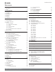
Installation Instructions Table of Contents 1 Key to Symbols and Safety Instructions 4 1.1 Key to Symbols 1.2 Safety 4 4 2 General Information 7 2.1 2.2 2.3 2.4 2.4 2.5 Included Items Optional Accessories Specifications Rating Plate Dimensions Components 7 7 8 9 10 11 3 Boiler Installation 13 3.1 Installer Qualifications 3.2 Compliance Requirements 3.3 Location 3.3.1 Access to Utilities 3.3.2 Humidity and Contact with Water 3.3.3 Drainage 3.3.4 Venting and Ventilation 3.3.5 Clearances 3.3.
Installation Instructions 1 Key to Symbols and Safety Instructions 1.2 Safety 1.1 Key to Symbols Please read before proceeding Warnings WARNING: FIRE, EXPLOSION Vapors from flammable liquids can explode and/or catch fire causing death or severe burns. Warnings in this document are identified by a warning triangle printed against a grey background. Keywords at the start of a warning indicate the type and seriousness of the ensuing risk if measures to prevent the risk are not taken.
Installation Instructions WARNING: FIRE, EXPLOSION Do not store combustibles, such as papers or laundry, near the boiler or venting system. Do not store or use gasoline or other flammable liquids near this boiler. Do not store or use compressed gases, such as hair sprays or spray paints, near the boiler or venting system, including the vent termination.
Installation Instructions 1.3 Important Note for the State of Massachusetts NOTICE BEFORE INSTALLATION This appliance must be installed by a licensed plumber or gas fitter in accordance with the Massachusetts Plumbing and Fuel Gas Code 248 CMR Sections 4.00 and 5.00. IMPORTANT: In the State of Massachusetts (248 CMR 4.00 & 5.
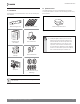
Installation Instructions 2 General Information 2.2 Optional Accessories 2.1 Included Items The following optional accessory is not included with the boiler, but may be necessary for the installation. Check the need for the following optional accessory before installation. The following items are included with the boiler. Check each of the following items before installation.
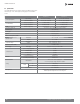
Installation Instructions 2.3 Specifications The following table shows the specifications for the boiler. Additional specifications about water, gas, electric, and air supplies (venting) appear in each installation section. Heat Capacity (Input) Flow Rate (DHW) AFUE Space Heating 19,900–80,000 BTU/H 19,900–140,000 BTU/H 19,900–155,000 BTU/H 19,900–199,000 BTU/H 45°F (25°C) Temp Rise 6.0GPM (23LPM) 7.7GPM (29LPM) 67°F (37°C) Temp Rise 4.0GPM (15LPM) 5.2GPM (20LPM) Natural Gas (propane) 95.
Installation Instructions 2.4 Rating Plate WARNING: FIRE, EXPLOSION The gas type and electricity voltage must match the rating plate. Using a different gas type and electricity voltage will cause the boiler to malfunction. Before the installation, check the rating plate located on the side of the boiler to ensure that the boiler matches the gas type, gas pressure, water pressure, and electrical supply available in the installation location.
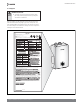
Installation Instructions 2.4 Dimensions D E F 0.36" (9.2 mm) C 1.8" (45.7 mm) H 5.26" (133.5 mm) 5.57" (141.5 mm) 2.2" (55.9 mm) 8.0" (203.2 mm) 4.7" (119.4 mm) 3.4" (86.4 mm) 2.8" (71.1 mm) 4.0" (101.6 mm) 6.1" (154.9 mm) 3.6" 2.7" 1.6" (40.6 mm) (91.4 mm) (68.6 mm) 11.61" (295 mm) 2.80" (71.1 mm) B 31.87" (809.5 mm) 27.56" (700 mm) A G 18.
Installation Instructions 2.
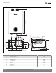
Installation Instructions Turbo fan assembly Ignition transformer Primary heat exchanger TDR damper Secondary heat exchanger Water Pressure Sensor Air Pressure Sensor PCB assembly Flow sensor Front panel Figure 6 12 | Singular Combi Boiler - BTC 439003301 B (2021/07)
Installation Instructions 3 Boiler Installation 3.3.1 Access to Utilities 3.1 Installer Qualifications Electricity – Close to where the electrical supply enters the building A licensed professional must install and inspect the appliance.
Installation Instructions 3.3.5 Clearances 3.3.6 Clean, Debris and Chemical-Free Combustion Air The boiler should be installed in an area that allows for service and maintenance access to utility connections, piping, filters, and traps. Ensure the following clearances are maintained: Do not install the boiler in areas where dust and debris may accumulate or where combustion air can be contaminated.
Installation Instructions 3.4 Mounting to the Wall To mount the boiler to the wall: 1. Check that the wall is level and can support the weight of the boiler. 2. Affix the mounting bracket securely to the wall. CAUTION: BODILY INJURY, PRODUCT DAMAGE The boiler is heavy. Always lift the unit with assistance. Be careful not to drop the boiler while lifting or handling it to avoid bodily injury or damage to the unit.
Installation Instructions 4 System Piping NOTICE: PRODUCT DAMAGE Before connecting the pipes to the boiler, clean all systems to remove sediment, flux, solder, scale, debris, or other impurities that may be harmful to the boiler system. It is important to maintain the inside of the pipes free of debris, copper dust, sand, and dirt while installing the heating system.
Installation Instructions Expansion Tank 4.1.3 Space Heating Piping The expansion tank should be installed in the system pipes in order to prevent excessive pressure in the heating pipes. When installing the expansion tank, follow the guidelines below. When connecting the space heating system, follow these guidelines. If the air separator is located on the suction side of the system circulator, connect the air separator to the expansion tank.
Installation Instructions Bosch is not responsible for the blockage of the domestic system due to the accumulation of foreign matters or scaling. The installer or the user should take appropriate measures in order to avoid any problem related to the quality of water. 4.2.3 DHW System Piping CAUTION: PERSONAL INJURY, PROPERTY DAMAGE In order to meet the requirements of ASME or CRN, an additional high temperature limitation device may be required.
Installation Instructions 4.3 Connecting the Condensate Drain NOTICE: BOILER DAMAGE, PROPERTY DAMAGE All condensate must drain and be disposed of according to local codes. Do not cap or plug the integrated condensate line. If prevented from draining, condensate can damage the boiler. The condensate line must have a negative slope to drain properly. Do not run drain outdoors. Freezing of condensate can cause property damage.
Installation Instructions 2. Place the free end of the drain line into an appropriate drain. 4.4 System Filling 4.4.1 Built-In Water Filling NOTICE: If you are using a condensate pump, ensure that the pump allows for up to 2 GPH of drainage for each boiler in the system. If you are not using a condensate pump, ensure that the drain line is pitched downward at a minimum slope of 1/4" per foot. 4.3.
Installation Instructions 4.5 Test the Water System 4.5.1 External Water Fill Connection Read and follow the guidelines below for system piping of the boiler. WARNING: PERSONAL INJURY, PROPERTY DAMAGE Ensure that the boiler is full of water before firing the burner. Operating the unit without filling it will damage the boiler. Such damage is not covered by the warranty, and may result in property damage, severe personal injury, or death.
Installation Instructions 4.6 Examples of System Applications Refer to the following examples to properly implement a system for space heating, DHW supply, or both. These examples are provided to suggest basic guidelines when you install the boiler system. However, the actual installation may vary depending on the circumstances, local building codes, or state regulations. Check the local building codes and state regulations thoroughly before installation, and comply with them fully. 4.6.
Installation Instructions 4.6.
Installation Instructions 4.6.3 System Application – Zone System with Circulators Zone 1 Zone 2 Zone 3 Check Valve System pump Purge Valve Air Separator Expansion tank Not to exceed 4 pipe Dia or Max.
Installation Instructions 5 Connecting the Gas Supply 5.1 Gas Pipe Sizing Tables Gas pipe sizing is based on the gas type, supplied gas pressure, pressure drop in the system, and gas line type. The tables below are for reference only (when the gas supply is piping straight to the boiler with no connections to any other gas appliances). For gas pipe sizing, refer to the latest National Fuel Gas code, NFPA 54 and consult the gas pipe manufacturer for actual gas pipe capacities.
Installation Instructions 5.2 Gas Piping 7. Connect the gas supply line. DANGER: FIRE, EXPLOSION Do not connect to an unregulated or high pressure propane line or to a high pressure commercial natural gas line. The boiler must be isolated from the gas supply piping system during any pressure testing of that system at test pressures equal to or more than 0.5 psig. WARNING: Only a licensed professional should connect the gas supplies.
Installation Instructions 5.3 Inlet Gas Pressure Gas Piping Examples: The following is a LP gas piping example for the single regulator system WARNING: Inlet gas pressure should be measured by a licensed professional only. The boiler cannot function properly without sufficient inlet gas pressure. The boiler must be isolated from the gas supply piping system during any pressure testing of that system at test pressures equal to or more than 0.5 psig.
Installation Instructions 8. When the boiler reaches its maximum firing rate, check the inlet gas pressure reading on the manometer. The gas pressure must fall within the ranges specified in "Specifications" on page 8. 2 2 Figure 27 9. Tighten the inlet gas pressure screw. 10. Replace the front cover and tighten the 2 Phillips screws to secure it to the case. 1 1 Figure 25 5. Loosen the screw indicated in the figure below and connect a manometer to the inlet pressure port.
Installation Instructions 6 Installing a Vent WARNING: CARBON MONOXIDE Improper venting of the boiler can result in excessive levels of carbon monoxide, which can lead to severe personal injury or death. This boiler must be vented in accordance with the “Venting of Equipment“ section of the latest edition of the ANSI Z223.1/NFPA 54 Natural Fuel Gas Code in the USA and/or the “Venting systems and air supply for boilers“ section of the latest version of the CAN/CGA B149.
Installation Instructions INSIDE AIL DET CORNER G D A H E B L B B C RABLE FIXED CLOSED OPERABL F OPE E FIXED CLOSED I M K B B J A B VENT TERMINAL AIR SUPPLY INLET AREA WHERE TERMINAL IS NOT PERMITTED Figure 29 Canadian Direct Vent Installations ¹) U.S. Direct Vent Installation ²) A Clearance above grade, veranda, porch, deck or balcony 12 in. (30 cm) 12 in. (30 cm) B Clearance to window or door that may be opened 36 in. (91 cm) 12 in.
Installation Instructions 6.1.2 Non- Direct Venting If, at any time, the installation location could experience negative pressure, there is a possibility of back-drafting cold air through the boiler’s heat exchanger. This situation could lead to the freezing of the heat exchanger and malfunction of the boiler. However, building codes in most jurisdictions disallow negative pressures in residences. In a home with a well-balanced air supply, the heat exchanger should not be in danger of freezing.
Installation Instructions INSIDE AIL DET CORNER G D A H E B L B B C OPERABL FIXED CLOSED E OPERABL F E FIXED CLOSED I M K B B J A B VENT TERMINAL AIR SUPPLY INLET AREA WHERE TERMINAL IS NOT PERMITTED Figure 31 Canadian Non-Direct Vent Installation ¹) U.S. Non-Direct Vent Installation ²) A Clearance above grade, veranda, porch, deck or balcony 12 in. (30 cm) 12 in. (30 cm) B Clearance to window or door that may be opened 36 in.
Installation Instructions 6.2 Vent Pipe Materials NOTICE: PCB DIP switch #1 is set to OFF as factory default WARNING: When you set PCB DIP switch #1 to ON, ensure that CPVC piping shall be used for exhaust venting. Venting requirements differ in the US and Canada. Consult the following chart or the most recent edition of ANSI Z223.1/ NFPA 54 or CAN/CGA B149.1, as well as all applicable local codes and regulations when selecting vent pipe materials.
Installation Instructions 6.3 Vent Length 6.4 Connecting the Vent Clip The maximum vent length when using 2" exhaust ducts is 60’. The maximum vent length when using 3" vent ducts is 150’. The intake duct length can be of equal length to the exhaust duct length.
Installation Instructions 6.5 Vent Termination 6.5.2 Two-Pipe Sidewall Venting Internal view WARNING: Air intake must be protected from any debris. Exhaust gas Intake air When connecting to the air intake connector and exhaust flue connector, all connecting parts must be installed properly. Maintain 12" (300 mm) min. (18" (450 mm) min. for Canada) clearance above highest-anticipated snow level. Maximum of 24" (600 mm) above roof.
Installation Instructions 6.5.3 Snorkel Flue 6.5.4 Non-Concentric Sidewall Venting 10" (254 mm) min. Schedule 40 PVC pipe 10" (254 mm) min. 12" (300 mm) min. 12" (300 mm) min. 12" (300 mm) min. Figure 41 Figure 40 NOTICE: Install a bird screen at the end of the intake air pipe and exhaust pipe. WARNING: Maintain 12" (300 mm) min. (18" (450 mm) min. for Canada) clearance above highest-anticipated snow level. Maximum of 24" (600 mm) above roof.
Installation Instructions 6.5.6 Two-Pipe Vertical Venting 6.5.7 Concentric Roof Venting 36" (900 mm) min. Vent Exhaust gas Combustion air Maintain 12" (300 mm) min. 12" (300 mm) min. From any obstruction (above, below, left, or right) 12" (300 mm) min. Intake air Combustion air Vent Figure 44 Figure 43 WARNING: Maintain 12" (300 mm) min. (18" (450 mm) min. for Canada) clearance above highest-anticipated snow level. Maximum of 24" (600 mm) above roof.
Installation Instructions 7 Setting the DIP Switches The boiler has a DIP switch on the main circuit board (PCB) Set the DIP switch appropriately, depending on the installation environment.
Installation Instructions 8 Connecting the Power Supply WARNING: Improperly connecting the power supply can result in electrical shock and electrocution. Follow all applicable electrical codes of the local authority having jurisdiction. In the absence of such requirements, follow the latest edition of the National Electrical Code (NFPA 70) in the USA or the latest edition of CSA C22.1 Canadian Electrical Code Part 1 in Canada.
Installation Instructions 9 Installation Checklist After the boiler installation, examine the following checklist. If you are not able to answer "Yes" to all of the items in the checklist, review the appropriate sections. To troubleshoot any operational problems, refer to "Troubleshooting" in the User's Manual. If there are additional questions or if you need assistance, contact technical support at 1-866-642-3198.
Installation Instructions Connecting a Pressure Relief Valve Check Have you installed an approved pressure relief valve on the boiler? Does the rating of the pressure relief valve match or exceed the maximum BTU rating of the boiler? Is the pressure relief valve 3/4 in on the hot water outlet and 3/4 in at the pressure relief valve adapter? Have you installed the pressure relief valve on the space heating and hot water outlet pipe near the boiler? Have you installed a discharge drain tube
Installation Instructions 10 Operating the Boiler 10.3 Setting the Space Heating Temperature 10.1 Turning the Boiler On or Off To turn the Boiler on or off, press the WARNING: button. If your household includes children, or elderly or disabled individuals, consider using a lower temperature setting. High temperatures circulating through baseboards or radiators can cause burns when touched. To set the space heating water temperature: 1. Press the MODE button until the icon turns on.
Installation Instructions 10.4 Setting the DHW (Domestic Hot Water) Temperature 10.5 Viewing Basic Information To turn the boiler on, press the WARNING: button. Water above 120°F (50°C) can cause instant scalding, severe burns, or death. To adjust the water temperature: 1. Press the Mode button until the icon turns on. Figure 52 To view information about the boiler, press the MODE and seconds. buttons for 5 Figure 50 2. Press the display.
Installation Instructions 10.5.1 H0 mode 10.5.3 H2 mode This is the mode for checking the previous error. This is the mode for checking the current error. H0 and the previous error (example: A6) will be displayed repeatedly on the screen. H2 and the current error (Example : A3) will be displayed repeatedly on the screen. Figure 54 Figure 56 10.5.2 H1 mode 10.5.4 H3 mode This is the mode for checking the most recent error.
Installation Instructions 10.5.5 H4 mode 10.5.7 H6 mode This is the mode for checking the current number of revolutions of the fan. This is the mode for checking the current exhaust gas temperature. H4 and the current number of revolutions of the fan (Example : 3600) will be displayed repeatedly on the screen. H6 and the current exhaust gas temperature (example: 120) will be displayed repeatedly on the screen. The unit is rpm. The unit is °F. Figure 58 Figure 60 10.5.6 H5 mode 10.5.
Installation Instructions 10.5.9 H8 mode 10.5.11 HA mode This is the mode for checking the current ambient temperature. This is the mode for checking the hot water and heating modes. H8 and the current ambient temperature (example: 25) will be displayed repeatedly on the screen. HA and the heating mode or the hot water mode (example: FF or 00) will be displayed repeatedly on the screen. The unit is °F. FF is the current hot water mode, and 00 is the heating mode.
Installation Instructions 10.5.13 Cd mode This is the mode for setting the cascade function of the heat only boiler and is not available for the combi boiler product line. 10.6 Setting the Heat Load for The Outdoor Reset Control Mode 1. Move No. 2 PCB DIP switch in the ON direction. ON 1 2 3 4 5 6 7 8 Figure 67 Figure 66 2. Make sure the touch pad display is powered off. Press the MODE and buttons for 5 seconds.
Installation Instructions When you set ON for C7 and press the MODE button, C8 and “1” will be displayed repeatedly. By pressing the MODE button, the user can enter modes such as C9, CA, Cb, and CC, and can set the temperature. You can set a value from 0 to 6 using the and buttons. (The factory default value is 1.) The meaning of each number is as follows.
Installation Instructions 10.7 Altitude Adjustment 4. Press and hold the and buttonsfor 5 seconds. These instructions shall address derating at altitudes above 2,000 ft. Boiler input ratings are based on sea level operation. No adjustments needed on installations up to 2,000ft. Adjust the program data based on altitude. See Table 24 below. Program Data Altitude Setting 0 ~ 1,999 ft 2,000 ~ 4,500 ft 50 55 P4 Table 24 How to program boiler: 1. Connect the power supply if not already done. 2.
Installation Instructions 11 Gas Conversion This boiler is configured for Natural Gas from the factory. If conversion to Propane Gas is required, the conversion kit supplied with the boiler must be used. DANGER: FIRE, EXPLOSION Inspect the packing between the gas valve and gas pipe whenever they are disassembled. The packing must be installed and must be in good condition. Failure to comply will cause a gas leak, resulting in severe personal injury or death.
Installation Instructions 3. Once the front cover is removed, place it in a safe location to prevent accidental damage. With the internal components exposed, locate the gas connector and the gas valve. Packing Orifice Gas connector Gas connector Gas valve Figure 78 4. Loosen the nut connecting the gas connector and the gas valve. Carefully separate the gas inlet pipe. Figure 80 7. Replace the old orifice piece and the packing with new part for use with LP gas.
Installation Instructions 9. Replace the gas connector and the gas inlet pipe to its original position and secure all connections. 3. Insert analyzer into the exhaust analyzer hole and measure the gas/air ratio (using combustion analyzer is recommended) 10. Turn on the gas and water supply to the boiler. Type 11.1 Combustion Analysis WARNING: Be sure to turn off the power before changing the DIP switch setting. High fire Low fire CO2 (%) CO2 (%) NG 9.5 ± 0.5 9.9 ± 0.5 LPG 9.5 ± 0.5 11.5 ± 0.
Installation Instructions WARNING: Be sure to turn off the power before changing the DIP switch setting. This boiler was converted on / / to with Kit No. 5. Set the DIP switch to maximum heat capacity operation. gas by (name and address of organization making this conversion, who accepts the responsibility for the correctness of this conversion). For more information about setting the DIP switches, refer to "Setting the DIP Switches" on page 38. 6.
| Brown Brown Pressure Sensor CIR MIN MAX CAS White Yellow RCOP OPTION Red Black White Black Black Green Red Black Purple Space Heating Supply Thermistor PRG RST Black Red Flame Rod Over Heat Thermostat Blue Blue DC FAN Flow Detect Switch Condensate trap Domestic Hot Water Thermistor Outdoor Thermistor OPTION Red Red White White Yellow Yellow Brown Brown Red Black Blue Space Heating Return Thermistor Ground Green Black White White Black T.D.
Installation Instructions 13 Ladder Diagram Figure 87 Singular Combi Boiler - BTC 439003301 B (2021/07) | 55
Installation Instructions 14 Normal Operating Sequence Power ON E E: Error check System Initalization E Yes DHW Mode DHW mode "A3" Error check "EE" Error check "A5" Error check "A4" Error check "E8" Error check "AB" Error check "A7" Error check "AC" Error check "A8" Error check "E1" Error check "AA" Error check "E3" Error check "AD" Error check "E0" Error check "E2" Error check "E4" Error check "E7" Error check E: Error check Remote Control ON? E "EF" Error check No E: Error c
Installation Instructions Heating operation T1 < T2 DHW operation No T3 < T4 No T1: Heating Temperature T3: DHW Temperature T2: Setting the heating Temperature T4: Setting the DHW Temperature Pre-purge Pre-purge PUMP ON PUMP ON FAN ON FAN ON Fan Motor Abnormal? Yes Fan RPM stabilized ? No "A2" Error check Fan Motor Abnormal? Yes APS Abnormal? Yes "A2" Error check "AE" Error check No Ignitor On Fan RPM stabilized ? No Gas Valve ON Ignitor On Flame Rod Abnormal? Yes "A6" Error
Installation Instructions 15 Outdoor Temperature Sensor 15.1 Outdoor Temperature Sensor Installation (Optional) 15.2 Outdoor Temperature Sensor Installation Guidelines Avoid installing the temperature sensor in a location where the temperature may change due to direct sunlight or a location where the representative outdoor temperature is not indicated. The best place to install the temperature sensor is to the north or northeast of the eaves, where direct sunlight can be avoided.
Installation Instructions 15.3 Outdoor Reset Control (Available with Optional Outdoor Temperature Sensor) The outdoor reset control can be used in order to improve the energy efficiency. With the Outdoor Reset Control, the space heating temperature setting automatically changes according to the outdoor temperature and the current space heating system application (system load). The outdoor reset control can be used only when the outdoor temperature sensor is installed.
Installation Instructions 16 Inspection and Maintenance Annual service and maintenance is required for the safe and long service life of the appliance, for efficient and economical operation, and to keep the environmental impact as low as possible. Owners/operators are encouraged to sign a service and maintenance contract with a trained and certified installer for annual servicing and maintenance of the boiler. 16.
Installation Instructions If there is no water supply valve, turn off the water supply at the water main. 7. Remove the strainer from the bottom of the boiler. 5. Remove the boiler front cover by loosening the 2 Phillips screws securing it to the case. 2 2 Figure 97 8. Close the drain valve when the water is completely drained. 9. Remove the cold water inlet filter. 10. Allow the residual water to drain from the boiler. 11.
Installation Instructions 16.2 Cleaning the Cold Water Inlet Filter To clean the cold water inlet filter: 1. Drain the boiler. Refer to Section 16.1 "Draining the Boiler ". 2. Remove the cold water inlet filter from the boiler. 2 2 1 1 Figure 98 3. Rinse the cold water inlet filter with clean running water. Figure 99 4. Remove the air intake filter located under the air intake connector. 4. Reinsert the cold water inlet filter. 5. Refill the boiler. Refer to "Draining the Boiler " on page 60. 16.
Installation Instructions 16.4 Protecting the Boiler from Freezing 16.5 Maintenance Schedules NOTICE: BOILER DAMAGE, PROPERTY DAMAGE To protect the boiler from freezing, recommend the use of a direct vent exhaust and intake system. Ensure that the exhaust vent pipe and the air intake pipe are both connected directly from the collars on the top of the boiler to the outdoors. This type of vent system minimizes air movement within the boiler.
Installation Instructions WARNING: Follow the service and maintenance procedures given throughout this manual and in component literature shipped with the boiler. Failure to perform the service and maintenance could result in damage to the boiler or system. Failure to follow the directions in this manual and component literature could result in severe personal injury, death, or substantial property damage. The boiler must be inspected annually by a qualified service agency.
Installation Instructions 17 Troubleshooting 17.1 Basic Problems If there is a problem with the boiler, refer to the following table for possible remedies. For minor problems, turning the boiler off and then turning back on may resolve the situation. If turning the boiler off and on and attempting the remedies Category Problem Boiler does not ignite.
Installation Instructions 17.2 Error Codes If an error code appears on the digital display, refer to the following chart for the reason, and a possible remedy for the situation. If the situation requires more support please contact Bosch at 866-642-3198. Error Code Cause Self-diagnosis/Action 1. Clean the intake air filter. A2 Abnormal operation: FAN 2. Check the fan connector. 3. Contact original installer or licensed professional.
Installation Instructions NOTES: Singular Combi Boiler - BTC 439003301 B (2021/07) | 67
United States and Canada Bosch Thermotechnology Corp. 65 Grove St. Watertown, MA 02472 Tel: 866-642-3198 Fax: 603-965-7581 www.bosch-thermotechnology.us BTC 439003301 B / 07.2021 Bosch Thermotechnology Corp. reserves the right to make changes without notice due to continuing engineering and technological advances.