INST-164 Licence Plate Recognition System Installation and Instruction Manual Reg-Sentry The following instructions assume a good working knowledge of the windows operating system. If you are networking this unit, it is assumed that you have a good working knowledge of network systems. If either of these assumptions are incorrect it advised that you consult an expert before attempting to install and commission the Reg-Sentry unit.
INST-164 Revision 4 Licence Plate Recognition Access Control System (REG-SENTRY) Installation Instructions Contents Page Description .............................................................................................................................3 Installation..............................................................................................................................3 Camera Installation ........................................................................................
INST-164 Revision 4 Description The Reg-Sentry is a self contained access controller that uses automatic licence plate recognition (ALPR). It requires a single video input (we recommend only using a Bosch security systems ALPR camera) and provides a switched relay output (NO/COM/NC) that can be utillised for access control.The switched output operates in conjunction with a user defineable black/white list that is downloadable to the Reg-Sentry via an ethernet (TCP/IP) connection .
INST-164 Revision 4 The maximum vertical view angle of an ALPR camera is 30 degrees. <30° The maximum horizontal view angle of an ALPR camera is 25 degrees. In most systems the horizontal angle and vertical angles are somewhere between 15 and 20 degrees. Avoid possible blocking objects in the view path of the camera such as (moveable) bars. Reg-Sentry Installation Wall Mounting The REG-SENTRY is supplied in a polycarbonate box, with 4.
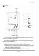
INST-164 Revision 4 Cable Connection Figure 4: Stand Alone Configuration There are five cable glands present on the Reg-Sentry (see fig 4). These glands will accommodate cables with an external diameter of 3mm to 6.5mm. Video Cable (Screw terminal type Reg-Sentry) At the top of the box is the video cable entry point. A good quality 75G video cable should be used between the camera and the Reg-Sentry. 1) Feed the cable into the top of the sentry unit through the cable gland.
INST-164 Revision 4 Video Cable (BNC type Reg-Sentry) At the top of the box is the video cable entry point. A good quality 75G video cable should be used between the camera and the Reg-Sentry. 1) Feed the cable into the top of the sentry unit through the cable gland. 2) Refer to BNC connector manufacturers instructions on how to attach the BNC to the internal end of the video cable. 3) Connect the BNC connector to the socket provided.
INST-164 Revision 4 Commissioning To commission the Reg-Sentry you will need to connect the unit to a PC using the network connector on the p.c.b. Use a standard network cable (Cat 5e) to make this connection. The following instructions assume a good working knowledge of the windows operating system. If you are networking this unit, it is assumed that you have a good working knowledge of network systems.
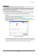
INST-164 Revision 4 6) Once connected, the password box will now appear in front of the viewer. Initially, the password is unset. Clicking on the ok button without entering any text into the box will give you full access to the sentry viewer. Figure 6: Password Box 7) The Sentry Viewer has a live video stream facility. This live video stream will however slow down the function of the Reg-Sentry significantly and is only provided as an aid to commissioning the unit i.e.
INST-164 Revision 4 8) The Settings menu has several functions and is activated by clicking on the “Settings” button, see fig 8. NB Please wait until the window is fully populated before attempting to change any of the settings. 8.1) The name of the sentry unit can be set by entering an appropriate name into the camera name text box 8.2) The onboard date can be set using the dropdown calendar. 8.3) The onboard time can be set using the “time” text box and the up/down arrows 8.
INST-164 Revision 4 9) The basic function of the Reg-Sentry is to compare captured licence plates with those stored on a list. To enter a single license plate onto the list, enter the text string (i.e. license plate) into the text box labelled “Black / White list”. Click the “ADD” button. This will add the license plate the list displayed on the sentry viewer. To upload the displayed list to the Reg-Sentry, click on the “Upload” button. The entire license plate list is then copied to the Reg-Sentry.
INST-164 Revision 4 Trouble Shooting Network Setting The default Reg-Sentry IP address is 192.168.0.204. It is possible that this IP address will be incompatible with your hardware i.e. it is not within the range of IP addresses that your server or computer will allow. If a non DHCP server is used or the device is connected directly to a PC / Laptop this incompatibility can cause the Reg-Sentry not to communicate with the computer running the Sentry Viewer software.
INST-164 Revision 4 Select “Internet Protocol (TCP/IP)” and then click on the “Properties” button. Figure 13: Internet Protocol (TCP/IP) Properties Select the “Use the following IP address” option and then enter the following IP address, 192.168.0.200. Enter the subnet mask as 255.255.255.0 N.B. Make a note of any current settings before changing the network settings. Once the pc network settings have been change you will be able to access the Reg-Sentry by typing 192.168.0.204 into your web browser.
INST-164 Revision 4 Figure 15:System Information Hyperlink Follow the change network settings hyperlink Figure 16: Change Network Settings Hyperlink Page 13 of 18
INST-164 Revision 4 Figure 17: Network Setting Page This page allows all the relevant network setting to be changed. Return to Default Setting In the event that your network settings are lost or incorrect, it is possible to return the Reg-Sentry unit to its default setting. NB the Reg-Sentry unit is statically sensitive and antistatic precautions should be observed during the following procedure. 1) Remove the power from the unit and then the lid.
INST-164 Revision 4 LED Location and Function Figure 19: LED Location DSP 1, Lit when a video input is detected. The LED is orange in colour. If this LED is not lit then you should inspect your video cable and ensure that your camera is functioning correctly. DSP 2, Lit when a live video stream is being provided to the sentry viewer, the LED is blue in colour. During normal operation the live stream should be switched off, you should always ensure that DSP2 is unlit after you have commissioned the unit.
INST-164 Revision 4 Figure 20: SentryViewer Interface Help Document Page 16 of 18
INST-164 Revision 4 Figure 21: Settings Menu Help Document Page 17 of 18
INST-164 Revision 4 This product complies with Electromagnetic Compatibility Directive meeting the following standards EN 61000-6-3: 2001, A11: 2004 EN 50130-4, A1: 1998, A2: 2003 EN55022: 2006 –Class A limits only FCC:2005 Parts 15.107 & 15.109 –Class A This equipment has been tested and found to comply with the limits for a class A digital device, pursuant to part 15 of the FCC rules.