Battery Charger PLN-24CH12 and PRS-48CH12 en Installation and Operation manual
Battery Charger Table of Contents | en 3 Table of Contents 1 Safety 5 2 Short Information 6 2.1 Purpose 6 2.2 Digital document 6 2.3 Intended audience 6 2.4 Related documentation 6 2.5 Alerts and notice signs 6 2.6 Conversion tables 7 3 System Overview 8 3.1 Application 8 3.2 Short description 8 3.3 Scope of delivery 8 3.4 Product view 9 3.4.1 Indicators on the front panel 3.4.2 Connections on the rear panel 10 9 4 Planning information 11 4.
en | Table of Contents Battery Charger 6.7.1 Mains power cable 24 6.7.2 Ground connection 24 7 Configuration 26 7.1 Battery charging 26 8 Operation 27 8.1 Working principles 27 8.1.1 Battery test 27 8.1.2 Battery undervoltage protection 27 8.1.3 Charging 28 8.1.4 Battery temperature compensation 29 8.2 Commissioning the system 29 9 Troubleshooting 30 10 Maintenance 31 11 Technical Data 32 11.1 Electrical 32 11.1.1 General 32 11.1.2 Fuses 32 11.
Battery Charger 1 Safety | en 5 Safety Prior to installing or operating this product, always read the Important Safety Instructions which are available as a separate document (F.01U.120.759). These instructions are supplied together with all equipment that can be connected to the mains supply. Safety precautions The battery charger is designed to be connected to the 230 Vac public distribution network.
en | Short Information Battery Charger 2 Short Information 2.1 Purpose The purpose of this Installation and Operation manual is to provide information required for installing, configuring, operating, maintaining and troubleshooting the battery charger. 2.2 Digital document This Installation and Operation manual is also available as a digital document in the Adobe Portable Document Format (PDF). Refer to the product related information on www.boschsecuritysystems.com. 2.
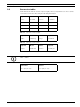
Battery Charger 2.6 Short Information | en 7 Conversion tables In this manual, SI units are used to express lengths, masses, temperatures etc. These can be converted to non-metric units using the following information. Imperial Metric Metric Imperial 1 in = 25.4 mm 1 mm = 0.03937 in 1 in = 2.54 cm 1 cm = 0.3937 in 1 ft = 0.3048 m 1m= 3.281 ft 1 mi = 1.609 km 1 km = 0.622 mi Table 2.1 Conversion of units of length Imperial Metric Metric Imperial 1 lb = 0.4536 kg 1 kg = 2.
en | System Overview Battery Charger 3 System Overview 3.1 Application The PLN-24CH12 (24 Vdc) and the PRS-48CH12 (48 Vdc) battery charger is intended for a Voice Alarm System. The battery chargers are microprocessor based devices that have been designed to charge lead-acid batteries (back-up batteries connected to the Voice Alarm System) and, simultaneously, to provide power to auxiliary applications. 3.
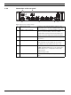
Battery Charger System Overview | en 3.4 Product view 3.4.1 Indicators on the front panel 9 xxV Battery Charger A B C Figure 3.1 Front view of battery charger A Status LED Green Yellow Mains status OK - Mains voltage threshold <165 Vac ±5% (Auto reconnect at >185 Vac ±5%). - Primary fuse (F1) is blown. - Power supply is broken. - Internal battery charger temperature is too high (>65°C). B Battery status OK - The battery is not present.
en | System Overview 3.4.2 Battery Charger Connections on the rear panel A B 7 1 8 9 2 3 4 5 D E 6 C F Figure 3.2 Rear view of battery charger A Mains power socket Socket for connecting the battery charger to the mains power. The socket has a built-in strain relief. B Auxiliary output terminals Three terminals for connecting auxiliary outputs (5 A max.) to power modules of the Voice Alarm System that do not have mains power inputs.
Battery Charger Planning information | en 4 Planning information 4.1 Overview 11 To find the right power back-up system for your needs, you will need to determine the exact conditions under which you will be utilizing a back-up system. Determining the amount of battery back-up you need for a system is not as simple as some other applications. Public address systems do not draw a constant current. The standard defines a standby time and an evacuation time.
4.3 en | Planning information Battery Charger Effects of discharge rate on battery capacity and battery life The rate at which a battery is discharged also has a profound effect on its capacity and life. Figure 4.1 shows the effect of discharge rate on battery capacity. The figure shows that a battery -when discharged at a low rate- will be able to deliver a higher capacity than a battery discharged at a high rate. A B Figure 4.1 Capacity vs discharge rate 4.
Battery Charger Planning information | en 13 Battery manufacturers typically recommend that you never discharge a deep-cycle battery below a certain percentage of its capacity. Usually 50% to 80% is recommended. The Vfinal value determines this (see section 8.1.2 ) 4.4.1 State of charge State of charge, or conversely, the depth of discharge can be determined by measuring the voltage and/or the specific gravity of the acid with a hydrometer.
en | Planning information Battery Charger Large battery banks make up a large thermal mass. Thermal mass means that because they have so much mass, they will change internal temperature much slower than the surrounding air temperature. For this reason, the external temperature sensor (see section 6.6 ) should be attached in thermal contact with the battery. The sensor will then read very close to the actual internal battery temperature. 4.
Battery Charger 4.7.3 Planning information | en 15 Sealed gel cell Gelled lead-acid batteries predate the AGM batteries but are losing to AGM. They have many of the same advantages over flooded lead-acid batteries including ease of transportation, as the AGM type, except the gelled electrolyte in these batteries is highly viscous and recombination of the gases generated while charging, occurs at a much slower rate.
5 en | Installation Battery Charger Installation Before installing the battery charger into the 19" rack, the battery jumper setting must be carried out. 5.1 Battery jumper setting The battery charger takes every 4 hours a resistance measurement (Ri) of the battery including connections and battery fuse if the total output current (main plus auxiliary) is <12 A.
Battery Charger 5.2 Installation | en 17 Rack mounting The battery charger has to be installed in a 19”rack that complies to Class 3k5 of EN60721-33:1995 +A2:1997 and IP30 of EN60529:1991+A1:2000. (See Figure 5.2). Figure 5.2 Rack mounting CAUTION! The openings provided in the cabinet must be kept free. Do not create additional openings because this can cause the device to malfunction and voids the warranty. Bosch Security Systems B.V. Installation and Operation manual 180110011Aa | V1.1 | 2011.
5.3 en | Installation Battery Charger EN54-4 labeling Please affix the regarding label clearly visible on the cabinet after installation. 180110011Aa | V1.1 | 2011.05 Installation and Operation manual Bosch Security Systems B.V.
Battery Charger 6 Connection | en 19 Connection A Faux3 Faux2 Faux1 B F6 F5 J F4 C F3 F1 F2 F1 D 9 8 G 7 6 5 4 3 H 2 1 I K M E L F Figure 6.1 Block diagram of the battery charger. Refer to table 6.1. Bosch Security Systems B.V. Installation and Operation manual 180110011Aa | V1.1 | 2011.
en | Connection Battery Charger F E H B A G I 3 2 1 6 5 4 3 2 1 C F8 M K D J F1 Figure 6.2 Top view PLN-24CH12 (24 Vdc). Refer to table 6.1. F E H B A G I 3 2 1 6 5 4 3 2 1 C F8 M K D J F1 Figure 6.3 Top view PRS-48CH12 (48 Vdc). Refer to table 6.1. 180110011Aa | V1.1 | 2011.05 Installation and Operation manual Bosch Security Systems B.V.
Battery Charger Connection | en Indication Description A Auxiliary output board B Main output board C Power and control board D Fault status LEDs E Temperature sensor / connection F Battery connection (+Batt and -Batt) G Auxiliary output fuses (Faux1 to Faux3) (5 A) H Main output fuses (F1 to F6) (32 A) I Output contacts connection (main, battery and output voltage status) J Fan K Daughter board L Battery fuse breaker (Not included.
6.1 en | Connection Battery Charger Connecting the battery CAUTION! For the PLN-24CH12 Battery Charger, the total sum of the batteries must be equal to 24 Vdc. For the PRS-48CH12 Battery Charger, the total sum of the batteries must be equal to 48 Vdc. When connecting multiple batteries, observe the following: – Only use batteries of the same voltage, capacity, type, brand and age. – Always connect the batteries in series. Figure 6.
Battery Charger 6.3 Connection | en 23 Connect the back-up power The battery charger has six (main) screw terminals for connecting to the Voice Alarm System. 1. Connect +Load (main) to the plus terminal of the system components. 2. Connect -Load (main) to the minus terminal of the system components. NOTICE! Do not use the main outputs to connect remote control panels or volume overrides. For this purpose, use the auxiliary output terminals. Refer to section 6.4 . 6.
en | Connection 6.6 Battery Charger Connect the temperature sensor The battery charger has one socket to connect the temperature sensor (which is packed with the system). 1. Plug the temperature sensor into the temperature sensor socket. 2. Attach the sensor body close to the battery, with good thermal coupling in order to get the correct temperature information. E.g. connect the sensor to the battery tray, or place it between the batteries. See Figure 6.6. 7 8 9 1 6 2 3 4 5 6 Figure 6.
Battery Charger Connection | en 25 CAUTION! Do not make a separate ground connection to the 24 Vdc or 48 Vdc output terminal. The outputs have a common return. Bosch Security Systems B.V. Installation and Operation manual 180110011Aa | V1.1 | 2011.
en | Configuration Battery Charger 7 Configuration 7.1 Battery charging CAUTION! If a mains failure occurs either on the battery charger, the connected system or on both (the system turns on ‘back-up operating’ mode, mains not present condition) an alarm must be generated on the Voice Alarm System. In normal operating mode: the battery charger (re)charges the batteries and maintains them when they are fully charged.
Battery Charger Operation | en 8 Operation 8.1 Working principles 8.1.1 Battery test 27 The battery presence test is performed in the following manner: The battery presence is tested every 30 seconds until 20 minutes after commissioning and every 15 minutes after. If battery absence is detected a fault is generated (refer to section 3.4.1 ). NOTICE! If a fault is detected, the test is performed every 30 seconds, until 20 minutes after resolving the fault.
en | Operation Battery Charger battery charger is switched-off (non-latching behavior) and all outputs are shut down. See Figure 8.1. – When the load is decreased below 12 A the battery charger is switch-on and connects the battery again to start the charging process. 8.1.3 Charging Figure 8.2 and Figure 8.3 show the charger voltage and the charge current versus the time during the charging process. Vbatt Vfloat A B t Figure 8.2 Charger voltage vs time A Bulk mode. B Float mode.
Battery Charger 8.1.4 Operation | en 29 Battery temperature compensation The battery charger has battery temperature compensation. The temperature is measured by the external temperature sensor (see section 6.6 ). Vfloat 28.5 / 56.9 27.2 / 54.4 26.2 / 52.4 -20 -10 0 10 20 30 40 50 60 70 Temp Figure 8.4 Temperature compensation for Vfloat The temperature compensation for Vfloat is: For PLN-24CH12: -40 mV / oC @ 25 oC. For PRS-48CH12: -80 mV / oC @ 25 oC. 8.
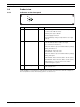
9 en | Troubleshooting Battery Charger Troubleshooting Problem Cause Solution Battery charger does not Mains fuse is broken. Check / replace fuse F1 (refer to start-up when the mains table 6.1 ). is connected (LEDs on Load on battery charger outputs Disconnect load on the main and battery charger are off). is to high (>12 A). auxiliary outputs until load is <12 A.
Battery Charger 10 Maintenance | en 31 Maintenance The battery charger has been designed to function without problems for a long time with a minimum of maintenance. In order to guarantee trouble-free operation, some cleaning and maintenance activities are required, which are described in this section. NOTICE! Maintenance should be done by qualified personnel only.
en | Technical Data Battery Charger 11 Technical Data 11.1 Electrical 11.1.
Battery Charger 11.2 11.3 Technical Data | en 33 Mechanical Dimensions (h x w x d) 44.5 x 483 x 310 mm (19” wide, 2RU high) Weight approx. 6 kg Environmental conditions Operating temperature range -5 to +45 oC Storage temperature range -25 to +85 oC Altitude Under 76 kPa, the max operating temperature decreases of 5°C every 10 kPa. Cooling operates transversely.
Bosch Security Systems B.V. Kapittelweg 10 4827 HG Breda The Netherlands www.boschsecurity.com © Bosch Security Systems B.V.