
Operation Manual
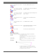
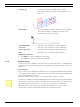


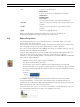


Table Of Contents
- IVA 4.0
- Table of Contents
- 1 Introduction
- 2 Requirements
- 3 Configuration
- 4 IVA 4.0
- 5 IVA 4.0 Flow
- 6 IVA and VG4 AutoDome
- 7 Display of Units of Measurement
- Index

IVA 4.0 IVA 4.0 Flow | en 49
Bosch Security Systems Operating Manual DOC | 4.0 | 2009.06
5 IVA 4.0 Flow
This chapter provides a description of the programm, the configuration and the various
IVA 4.0 Flow settings.
5.1 The Basics and Image Information
The IVA 4.0 Flow approach differs from the IVA 4.0 object recognition. This function detects
an optical flow formed by the movement of individual blocks. The camera does not need to be
calibrated. The size of a detected object is irrelevant.
Depending on the IVA 4.0 Flow configuration, additional overlays in the image can provide
further information.
Flow Detection Notes and Limitations
If the computing power is reduced because of enhanced encoding power, fast speeds can no
longer be detected.
Optimum flow detection is recorded at speeds of two to eight seconds (throughput time in
the sensitive area). Very fast and slow movements are not detected as a flow.
Objects that are smaller than 1% of the image area do not trigger flow detection.
Textured objects that stand out from the background are more likely to be detected than
those that are similar.
Objects that move backward and forward or move in a zig zag do not trigger flow detection.
An object can only trigger flow detection if it predominantly moves in a straight line. However,
if objects are temporarily concealed by a tree, for example, detection is not restricted.
5.2 IVA 4.0 Flow User Interface
The following descriptions and screenshots relate to the user interface as it appears in
Configuration Manager.
All tabs are combined in a dialog box in the Web browser view. The preview on the VCA
configuration page is used as the camera image.
The configuration options are identical.
X To open the online Help for IVA 4.0 click the area you are interested in and press F1.
Description
Red arrows indicate a detected flow that will generate an alarm event in
accordance with the current settings.
Yellow arrows indicate a detected flow that will not generate an alarm event.
The arrows indicate the direction of movement of the detected block. The
length of an arrow indicates the speed of the block. This ensures that
movements that have been defined in more detail can be filtered out and will
not trigger an alarm.