IVA 4.
IVA 4.0 Table of Contents | en 3 Table of Contents 1 Introduction 5 1.1 Welcome to the IVA Intelligent Video Analysis Help 5 1.2 About this Manual 5 1.3 Conventions in this Manual 5 1.4 Intelligent Video Analysis 5 2 Requirements 7 2.1 Setup 7 2.2 Forensic Search in Recordings 7 2.3 License 7 2.4 Limitations 9 3 Configuration 11 3.1 Configuration with Configuration Manager 11 3.2 Configuration Using Web Browser 12 4 IVA 4.0 14 4.1 The Basics 14 4.
en | Table of Contents IVA 4.0 5.2 IVA 4.0 Flow User Interface 49 5.2.1 Popup Menu in the Camera Image 51 5.3 Tasks 52 5.4 Creating/Editing a Task 53 5.4.1 Default Task 53 5.4.2 Tampering 53 5.4.3 Flow in field 54 5.4.4 Counterflow in field 55 5.5 Statistics 56 5.6 Configuration 57 5.6.1 Sensitivity Settings 57 6 IVA and VG4 AutoDome 58 7 Display of Units of Measurement 59 Index 60 DOC | 4.0 | 2009.
IVA 4.0 Introduction | en 1 Introduction 1.1 Welcome to the IVA Intelligent Video Analysis Help 1.2 About this Manual 5 This manual is intended for persons who will operate IVA 4.0 or IVA 4.0 Flow. The manual describes how to operate IVA 4.0 or IVA 4.0 Flow. 1.3 Conventions in this Manual In this manual, the following symbols and notations are used to draw attention to special situations: CAUTION! Security instructions where non-compliance can result in loss of data are marked with this symbol.
en | Introduction IVA 4.0 – Camera calibration for IVA 4.0: Enhanced calibration options with a choice of two calibration modes. DOC | 4.0 | 2009.
IVA 4.0 Requirements | en 2 Requirements 2.1 Setup 7 The easiest way to set up IVA 4.0 and IVA 4.0 Flow is using the Configuration Manager program. This must be installed on a Windows PC that can communicate with the respective device over a network. You will find a current version of the Configuration Manager program on the CD received when you purchased the license. Operational requirements for the Configuration Manager program can be found in the documentation supplied.
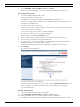
en | Requirements IVA 4.0 2. Select SETTINGS > Advanced Mode >Service > Licenses. Make a note of the installation code — the copy-and-paste function is supported. Requesting Activation Keys 3. Open the following Website from any PC: https://activation.boschsecurity.com/ You will find a direct link to this Website under Tools on the IVA 4.0 CD. The Bosch Security Systems Software License Manager user interface will appear. The page appears in English only. 4. If you already have an account, log in.
IVA 4.0 Requirements | en 9 13. Close the window. IVA 4.0 is now activated. The activation key can no longer be seen. Upgrade from IVA 3.5 If you have already licensed IVA 3.5 for the device, you simply need to upgrade the firmware of the device to version 4.0 or higher. The license for IVA 3.0 is then automatically changed to an IVA 4.0 license. Relicensing is not necessary. You obtain the current firmware from your customer service or from the download area on our Internet site.
en | Requirements IVA 4.0 If you are specifically looking for moving objects with certain color properties, take the following into consideration: – An object is almost never displayed in a consistent color in the image data. Pixels on the outer edge of a detected object in particular often contain the color information of the background and not the object. Objects such as automobiles comprise a variety of parts (body, windows, tires).
IVA 4.0 3 Configuration | en 11 Configuration IVA 4.0 and IVA 4.0 Flow are set up using the Configuration Manager program or via the Web browser view of the device. You must move the camera to the required position first in each case. When using VG4 AutoDome, the individual presets must be specified before configuring IVA 4.0 for each preset. All of the settings you make relate to the selected camera position. This means that you must reconfigure IVA 4.
en | Configuration IVA 4.0 7. Select IVA 4.0 or IVA 4.0 Flow as the Analysis type. If you change the analysis type, the motion detection and tamper detection parameters revert to the default settings. As soon as the analysis becomes active, meta data is generated and, depending on the configuration, additional information is overlaid on top of the camera image — an object bounding box for example. 8. Click Configuration.... The IVA Wizard window opens. IVA 4.0 and IVA 4.
IVA 4.0 Configuration | en 13 Alarm status This field shows whether IVA 4.0 has generated an alarm event with the current settings. Bosch Security Systems Operating Manual DOC | 4.0 | 2009.
en | IVA 4.0 4 IVA 4.0 IVA 4.0 This chapter provides a description of the program, the configuration and the various IVA 4.0 settings. For details on configuring IVA 4.0 Flow, please refer to: Section 5 IVA 4.0 Flow, page 49. 4.1 The Basics The camera 'sees' a selected area. This area is displayed in the Configuration Manager program as a single, constantly refreshed image. In the Web browser view of the device you will see a live video preview.
IVA 4.0 IVA 4.0 | en 15 Route Objects that move along a route you have defined in a pre-defined direction can trigger an alarm event. It is possible to include deviations from this route using the relevant tolerance defaults. NOTICE! You can create up to 16 fields, 16 lines and 8 routes (as routes are counted twice). The total sum of these items cannot be greater than 16. If this limit is reached, no additional items can be created.
en | IVA 4.0 IVA 4.0 Configuration > Global Objects that are smaller than the minimum size setting or Settings larger than the maximum size setting are ignored. Idle or removed objects are only detected if the relevant option is activated in this case. (See: Section 4.7.2 Global Settings, page 44) Configuration > Sensitive Area Objects outside the sensitive area are basically ignored. Retrospective searches for movements in recordings can only be carried out within this area. (See: Section 4.7.
IVA 4.0 IVA 4.0 | en 17 Description A yellow flag marks the currently selected object. The properties of this object can be displayed when a task is created. An object can only be selected if you have selected the Object Properties tab (see: Section 4.8 Object Properties, page 47) or if you process the Approximation (see: Section Next Step - Approximation, page 24) step when creating a task.
en | IVA 4.0 IVA 4.0 3 Configuration When this tab is selected, you can access all of the necessary basic settings: – Calibration (see: Section 4.7.1 Calibration, page 39) – Global Settings (see: Section 4.7.2 Global Settings, page 44) – Sensitive Area (see: Section 4.7.3 Sensitive Area, page 46) 4 Object Properties The properties are displayed here for a marked object.
IVA 4.0 4.3.1 IVA 4.0 | en 19 Popup Menu in the Camera Image The popup menu in the camera image allows you to create, edit and delete fields, lines and routes. It gives you access to display options. You can also start the IVA Task Editor. X Right-click in the camera image in order to display the popup menu. Depending on whether you click an object or free space, various commands are available. If the Statistics tab is selected, then no popup menu is available.
en | IVA 4.0 IVA 4.0 – Show From the submenu, select the items to be displayed in the camera image: – Sensitive Area The area marked as sensitive is shaded in yellow. (See: Section 4.7.3 Sensitive Area, page 46) – Object Outlines Objects that are detected as moving are highlighted with a yellow outline. A red line indicates an object that has triggered an alarm event. – Object Bounding Boxes The object bounding box is the rectangle enclosing the object.
IVA 4.0 IVA 4.0 | en 21 Editing a Line A line can be edited at any time. This includes: – Moving end points – Moving lines To change the line, place the mouse cursor on an end point and move it while holding down the mouse button. To move the line, place the mouse cursor on the line and move it while holding down the mouse button. If a line is integrated into a task, you can choose the direction in which the line must be crossed in order to trigger an alarm.
en | IVA 4.0 4.3.2 IVA 4.0 The IVA Task Editor The IVA Task Editor offers access in script form to the total configuration of the Video Content Analysis you have created. All items (fields, lines, routes) and all tasks are displayed using the IVA Task Script Language. NOTICE! Only change the script if you are familiar with the IVA Task Script Language. You can find the relevant documentation on the IVA 4.0 CD. Creating a Backup with the IVA Task Editor 1.
IVA 4.0 IVA 4.0 | en – An object stops in certain areas without any target-specific movement (loitering). – An object moves along a defined route. – A piece of luggage is set down (idle object). – An object is removed (theft). – The camera is tampered with. 23 Some of the tasks, such as head detection and the identification of similar objects are primarily used for forensic searches on recordings. The result of a task is an alarm event.
en | IVA 4.0 IVA 4.0 – Section 4.5.7 Tampering, page 34 The camera is tampered with. – Section 4.5.8 Removed object, page 35 A previously idle object disappears, for example, in the event of theft. – Section 4.5.9 Idle object, page 35 A previously moving object is at rest, for example, a piece of luggage is set down. – Section 4.5.10 Entering field, page 36 An object enters a defined field. – Section 4.5.11 Leaving field, page 36 An object leaves a defined field. – Section 4.5.
IVA 4.0 IVA 4.0 | en 1. 25 Click a moving object in the camera image. The object is marked with a yellow flag. The properties of the marked object are displayed in the wizard. The properties of an object are always changing. You adopt the properties of the object at the time of clicking. The values for object size, aspect ratio, speed and direction are displayed for the marked object. The colors of the object are also displayed in proportional sequence. 2.
en | IVA 4.0 IVA 4.0 1 Visualization of the property In this example, the visualization of the aspect ratio is displayed. 2 Marked object The marked object whose properties are described is marked with a yellow flag. 3 Property activated In this example, the Aspect ratio v/h property is used to describe an object. NOTICE! You can switch to the Object Properties tab at any time (see: Section 4.8 Object Properties, page 47).
IVA 4.0 IVA 4.0 | en 27 Speed [km/h] Only objects moving at a speed that corresponds to the entered values generate an alarm event. X Enter a minimum and a maximum value for the speed. NOTICE! The speed of a movement at a right angle to the camera can be determined much more accurately than the speed of a movement directly toward or away from the camera.
en | IVA 4.0 IVA 4.0 Next Step - Define the Color In this step, you describe the color property of the searched object. Colors are described in IVA 4.0 using the HSV color model. – H - Hue The hue is the color that is reflected from an object. The hue is measured as a position on the color wheel and is given as a value between 0° and 360°. – S - Saturation The saturation is the intensity of the color.
IVA 4.0 IVA 4.0 | en 2 29 Value Use this slide control to select the degree of brightness for the colors. The number of colors to be taken into account is displayed according to the other settings. The display shows a higher or lower section of the color cylinder according to the slide control setting. 3 Colors You can manually adopt colors from the color cylinder for the search. To do this, set the value first and then click the desired color segment using the mouse.
en | IVA 4.0 IVA 4.0 Use head detection filter 1. 2. Activate this option if you wish to filter objects based on head detection. Select one of the options: – Limit to objects where no head has been detected Alarm events are only triggered for objects on which no head is detected. – Limit to objects with a largest head width between Triggers an alarm event for objects on which a head of the specified size has been detected.
IVA 4.0 IVA 4.0 | en 31 Next Step - Approximation You can impose approximations for the different object properties. You can adopt these values as the basis for the settings in the next step. These settings are described here: Section Next Step - Approximation, page 24. Next Step - Define the Conditions You limit the number of objects that trigger an alarm event by precisely defining properties such as size, aspect ratio, speed and direction.
en | IVA 4.0 IVA 4.0 Final Step - Define the Head Detection Conditions In this step, you define whether an alarm should be triggered according to whether or not detected objects have a head. This enables you to set the surveillance to focus on people or exclude them completely. These settings are described here: Section Final Step - Define the Head Detection Conditions, page 29. 4.5.
IVA 4.0 IVA 4.0 | en 33 Final Step - Define the Head Detection Conditions In this step, you define whether an alarm should be triggered according to whether or not detected objects have a head. This enables you to set the surveillance to focus on people or exclude them completely. These settings are described here: Section Final Step - Define the Head Detection Conditions, page 29. 4.5.6 Following route This task generates an alarm event if an object moves along a certain route.
en | IVA 4.0 IVA 4.0 Next Step - Define the Conditions You limit the number of objects that trigger an alarm event by precisely defining properties such as size, aspect ratio, speed and direction. These settings are described here: Section Next Step - Define the Conditions, page 25. Next Step - Define the Color You limit the number of objects that trigger an alarm event by defining the color properties more precisely. These settings are described here: Section Next Step - Define the Color, page 28.
IVA 4.0 4.5.8 IVA 4.0 | en 35 Removed object This task generates an alarm event if an object is detected as removed in a certain area (for example, due to theft). The area is defined by a field in the camera image. It is assumed that an object has been removed if changes are detected in the background following movement within an image. First Step - Define the Field X Select one of the fields. To do this, use the list field or click a field in the camera image.
en | IVA 4.0 4.5.10 IVA 4.0 Entering field This task generates an alarm event if an object enters an area. The area is highlighted by a field in the camera image. The alarm event is triggered if an object that was previously detected outside a field crosses the field boundary. First Step - Define the Field 1. Select one of the fields. To do this, use the list field or click a field in the camera image. You can also create a new field, edit an existing one or select Whole screen. 2.
IVA 4.0 IVA 4.0 | en 2. 37 Debounce time [s] If a value other than 0 (zero) is selected, the alarm event will not be generated until the object has moved or been outside the field for the specified period at least. By entering a value, you can prevent the triggering of multiple alarm events by objects that are constantly moving toward and away from the boundary of the field. Next Step - Approximation You can impose approximations for the different object properties.
en | IVA 4.0 IVA 4.0 3. For each of the properties, select how exactly they must correspond for an object to be detected as being similar to this object. The Precision slide control sets the accuracy progressively. – Slide control set to the left: Property is ignored. – Slide control set almost to the left: Property is considered, correspondence can be very inaccurate. – Slide control set to the right: Property is considered, correspondence must be very accurate.
IVA 4.0 IVA 4.0 | en – Section 4.7.2 Global Settings, page 44 – Section 4.7.3 Sensitive Area, page 46 39 The settings and values defined here are valid for all tasks. 4.7.1 Calibration Calibration is necessary for specifying the relationship between the camera image and the real-life environment. Areas and speeds can be correctly interpreted after the camera angle, camera elevation and distance are entered.
en | IVA 4.0 IVA 4.0 Focal length [mm] This value can be found in the camera calibration. Sensor size This value can be found in the camera calibration. Sensor aspect ratio This value can be found in the camera calibration. 2. Place at least two calibration elements on the camera image. Use these calibration elements to trace individual outlines of the displayed environment in the camera image and define the positioning and dimension of these lines and angles.
IVA 4.0 IVA 4.0 | en 41 The Error color field indicates the deviation of the plotted calibration elements from the perceived actual situation. – red: significant deviation. – yellow: minimal deviation. – green: length of the plotted lines and angles indicate the actual situation. Once you have clicked Adapt Elements, the field will always be displayed in green. The tooltip indicates the deviation of the elements you created from the suggested elements.
en | IVA 4.0 IVA 4.0 Applying the Calibration 1. Click Apply to save the calibration for this image. 2. Click Cancel to return to the last saved calibration. Calibrating with Calibration Plane The calibration is defined by placing a virtual plane on the camera image and adjusting it stepby-step in relation to the actual situation. With a VG4 AutoDome, calibration must be completed for each preset. The settings are graphically displayed on the camera image by the virtual plane and two cubes.
IVA 4.0 IVA 4.0 | en Anchor point center of the 43 The entire calibration plane is moved. plane One of the lines of the plane The calibration plane is tilted horizontally; the that is horizontal in the start tilt angle is changed. position One of the lines of the plane The calibration plane is tilted vertically; the roll that is vertical in the start angle is changed. position Anchor point lower corner of The perspective of the calibration plane is the plane distorted.
en | IVA 4.0 IVA 4.0 Roll angle [°] The angle by which the calibration plane is tilted. The setting can deviate from the horizontal by up to 10 degrees. Elevation [m] The vertical distance from the camera to the ground plane of the captured image – typically the elevation of the mounted camera above the ground. Focal length [mm] This value can be found in the camera calibration. Sensor size This value can be found in the camera calibration.
IVA 4.0 IVA 4.0 | en 45 Head Detection 1. Activate this option if you wish to use head detection. Two head outlines, representing the minimum and maximum size of the heads to be identified, will be displayed in the camera image. 2. Move one of the outlines onto a head that is displayed in the camera image and adapt the size or enter the corresponding values in the input fields. Avoid false alarms and reduce required computing power by restricting head detection to the expected head sizes.
en | IVA 4.0 IVA 4.0 – Enhanced separation – Activated: Improves the detection and separation of objects that move in close proximity to one another. This option requires additional computing power. – Deactivated: Objects moving in close proximity to one another may blend into one object. Advantages and disadvantages of the individual setting depend on the captured image. Reset Click here to reset all settings to their initial conditions. Apply Click here to apply all settings. 4.7.
IVA 4.0 IVA 4.0 | en Tool 47 Selection of an editing tool. Rubber Band You can use the mouse to draw any size of square. Small Square Medium Square Large Square You can edit the sensitive area as with a drawing tool. Clear All Click here to define the whole of the captured area as nonsensitive. Set All Click here to define the whole of the captured area as sensitive. Apply Click here to apply all settings. While you are drawing, hold down the SHIFT key to create non-sensitive areas.
en | IVA 4.0 IVA 4.0 The illustration of the color columns is also updated once every second. It changes when the color property of the marked object changes. Colors that appear as less than 5% are not displayed. Colors cannot be detected for very small objects. NOTICE! If a marked object leaves the sensitive area, the properties can no longer be monitored. This also applies to objects that do not move for a longer period of time. The value display no longer changes if this is the case.
IVA 4.0 5 IVA 4.0 Flow | en 49 IVA 4.0 Flow This chapter provides a description of the programm, the configuration and the various IVA 4.0 Flow settings. 5.1 The Basics and Image Information The IVA 4.0 Flow approach differs from the IVA 4.0 object recognition. This function detects an optical flow formed by the movement of individual blocks. The camera does not need to be calibrated. The size of a detected object is irrelevant. Depending on the IVA 4.
en | IVA 4.0 Flow IVA 4.0 1 Tasks When this tab is selected, you can see all the defined tasks. You have the option to create new tasks and to edit or delete existing ones. (See: Section 5.3 Tasks, page 52) 2 Statistics When this tab is selected, the statistics for the detected flows are displayed. (See: Section 5.5 Statistics, page 56) 3 Configuration When this tab is selected, you can access all of the necessary basic settings: – Sensitivity Settings (see: Section 5.6.
IVA 4.0 IVA 4.0 Flow | en 51 CAUTION! Changes to task settings take effect immediately. Configuration and tamper settings only take effect once they have been saved in Configuration Manager. Settings are only saved permanently when you click in Configuration Manager or click Save configuration in the Web browser view. 5.2.1 Popup Menu in the Camera Image The popup menu in the camera image allows you to create, edit and delete fields. It gives you access to display options.
en | IVA 4.0 Flow IVA 4.0 A field that is not being used in any tasks is displayed in gray. A field that is being used in a task is displayed in green. Used fields can be edited but not deleted. A field for which there is currently an alarm event is displayed in red. 5.3 Tasks This tab is displayed when you click Configuration... in the VCA tab in Configuration Manager. Before defining tasks, specify the sensitive area and the motion detection parameters: – Section 5.6.
IVA 4.0 IVA 4.0 Flow | en New 53 Click here to create a new task. Instead of the task list, the window for selecting a wizard is displayed. Edit Click here to edit a selected task. The wizard that was displayed for the creation of the task is reopened. You can change individual parameters. Delete 5.4 Click here to delete a selected task. Creating/Editing a Task A task is always created or edited using a wizard. The following wizards are available: – Section 5.4.
en | IVA 4.0 Flow IVA 4.0 – Scene too dark Activate this function if tampering associated with covering the lens (for instance, by spraying paint on it) should trigger an alarm. The average brightness of the scene provides a basis for recognition. – Signal loss Activate this function if the interruption of the video signal should trigger an alarm. – Reference check Activate this function if a deviation from the reference image on the standard configuration page should trigger an alarm. 5.4.
IVA 4.0 IVA 4.0 Flow | en 55 An activity that is to trigger an alarm event can be restricted. Change the values if you do not want a particularly low or high activity to trigger an alarm. 1. Activate this option if you wish to filter flows based on their activity. 2. Enter a minimum and a maximum value for the activity. The selected values are displayed on the camera image during input by a respectively high number of yellow dots.
en | IVA 4.0 Flow IVA 4.0 Adaption time window [s]: Specify the period during which there must be activity for a main flow to be detected. In this context, an activity is the percentage of the monitored area in which a flow is detected. As soon as a main flow is detected as such, the counterflow will also be detected. Activity [%] The activity of the counterflow that is to trigger an alarm event can be restricted.
IVA 4.0 IVA 4.0 Flow | en 57 Green: set of flows with no alarm Red: set of flows with alarm Click Reset to begin building statistics again. 5.6 Configuration This tab provides access to basic settings that you should specify before defining the individual tasks. The settings and values defined here are valid for all tasks. 5.6.1 Sensitivity Settings Sensitive Area The sensitive area is that part of the image seen by the camera that is analyzed.
en | IVA and VG4 AutoDome 6 IVA 4.0 IVA and VG4 AutoDome If you implement IVA 4.0 or IVA 4.0 Flow with VG4 AutoDome, please note the following: – There are ten different profiles available for configuring IVA 4.0 (see also: Section 3.1 Configuration with Configuration Manager, page 11). Each profile can be assigned to a different preset. Each preset can have its own IVA configuration. Define the camera positions for the individual presets before starting to configure IVA 4.0.
IVA 4.0 7 Display of Units of Measurement | en 59 Display of Units of Measurement In the English-language user interface in the Configuration Manager program, you can display units of measurement according to the Anglo-American measurement system. 1. Close the Configuration Manager program. 2. Click Start > My Computer. 3. Right-click in the window and select Properties from the popup menu. The System Properties window opens. 4. Click the Advanced tab. 5. Click Environment Variables.
en | Index IVA 4.
IVA 4.0 Index | en 61 Task alarm 23, 52 creating 23, 53 default 24, 53 deleting 23, 53 editing 23, 53 entering objects 36 explanation 15 leaving area 36 name 23, 52 similarity search 37 Task Editor 22 Tasks 22, 52 Tilt angle 39, 43 U Units of measurement 59 Using a property 25 V VCA (tab) 11 Video errors 34, 53 W Wizard explanation 15 Y Yellow flag 17 Bosch Security Systems Operating Manual DOC | 4.0 | 2009.
en | Index DOC | 4.0 | 2009.06 IVA 4.
Bosch Security Systems Robert-Koch-Straße 100 D-85521 Ottobrunn Germany Telefon 089 6290-0 Fax 089 6290-1020 www.boschsecurity.