
Specifications


Data sheet
BMA220
Page 39
BST-BMA220-DS003-08 | Revision 1.15 | August 2011 Bosch Sensortec
© Bosch Sensortec GmbH reserves all rights even in the event of industrial property rights. We reserve all rights of disposal such as copying and passing on to
third parties. BOSCH and the symbol are registered trademarks of Robert Bosch GmbH, Germany.
Note: Specifications within this document are subject to change without notice.
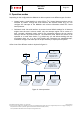
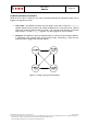
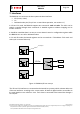
7.1 General digital interface description
In general there are two common digital protocols selectable, the serial interfaces I²C and SPI.
By default, SPI is used in the standard 4-wire configuration. The SPI interface may be
configured by SW to operate in 3-wire interface mode, instead of standard 4-wire mode.
The two serial interfaces are mapped onto the same pads. An external pin is needed to switch
between the interfaces. When this protocol select pin (PS) is connected to VSS, SPI is selected
as the current interface; when the select pin is connected to V
DDIO
, I²C is used as the interface.
When select pin is left floating, one of the dedicated modes is selected.
The BMA220 doesn’t provide a functional analog output of the three axes since there is just
CAP0 available in the package.
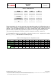
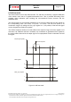
Table 19: Interface pin name
PIN Name PIN description
CSB SPI serial enable bar
SCK/SCL
SPI serial clock (SCK)
I²C serial clock (SCL)
SDI/SDO/SDA
SPI serial data input (SDI)
SPI serial data output in 3-wire SPI mode (SDO)
I²C serial data (SDA)
SDO SPI serial data output