
Specifications

Data sheet
BMA220
Page 28
BST-BMA220-DS003-08 | Revision 1.15 | August 2011 Bosch Sensortec
© Bosch Sensortec GmbH reserves all rights even in the event of industrial property rights. We reserve all rights of disposal such as copying and passing on to
third parties. BOSCH and the symbol are registered trademarks of Robert Bosch GmbH, Germany.
Note: Specifications within this document are subject to change without notice.
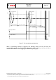
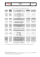
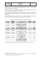
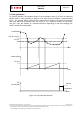
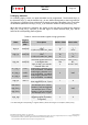
Table 12: Control and status register for low-g detection
Name
Register
Address
(SPI) *
Description Number of bits Reset-value
Low_th 0x06[7:4]
define the low-g threshold level
1 LSB is 2*(LSB of acc_data)
LOW_TH_NUM
4
LOW_TH_INIT
“0100”
Low_hy 0x07[7:6]
define the low-g hysteresis level
1 LSB is 2*(LSB of acc_data)
LOW_HY_NUM
2
LOW_HY_INI
T
“01”
low_dur 0x07[5:0]
define the number of measured
data which has to be lower than
low_th+low_hy to set the
interrupt (max. 64)
LOW_DUR_NUM
6
LOW_DUR_IN
IT
“111111” (3F)
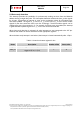
en_low 0x0E.3
enable signal for low-g
detection
1 ‘0’
low_int 0x0C.3
whether low-g interrupt has
been triggered (0=no, 1=yes)
1 ‘0’
* For determining the corresponding I
2
C register address, please refer to figure 2 in chapter 4 (memory map)