
Specifications

Data sheet
BMA220
Page 26
BST-BMA220-DS003-08 | Revision 1.15 | August 2011 Bosch Sensortec
© Bosch Sensortec GmbH reserves all rights even in the event of industrial property rights. We reserve all rights of disposal such as copying and passing on to
third parties. BOSCH and the symbol are registered trademarks of Robert Bosch GmbH, Germany.
Note: Specifications within this document are subject to change without notice.
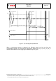
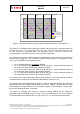
The given specification is valid for an upright mounted PCB. In order to enable also horizontal
mounting, x and z axis can be exchanged via the register orient_ex. The x-, y-, z-axis will keep
right-hand principle after the exchange.
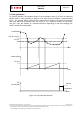
When serial interface is active, orientation detection is enabled if the enable bit en_orient is set.
To disable the orientation interrupt, clear the enable bit.
When the dedicated orientation mode is active, the orientation is given by certain output pins
corresponding to the above-given definition of the orient register. For details on the output pins
see section 6.1.
In case the orientation interrupt condition has been satisfied and interrupt is not latched, int
signal is asserted for one data sampling period unless no-reset condition applies.
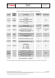
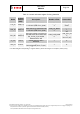
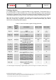
Table 11: Control and status register for orientation recognition
Name
Register
Address
(SPI) *
Description
Number of
bits
Reset-
value
orient_ex 0x09.7
exchange x- and z-axis in
algorithm, i.e x or z is relevant axis
for upward/downward looking
recognition (0=z, 1=x)
1 ‘0’
Orient 0x0B[6:4]
give the orientation of the sensor
with respect to the gravitational
force
3
ORIENT
_INIT
‘000’
orient_int 0x0B.7
whether orientation interrupt has
been triggered (0=no, 1=yes)
1 ‘0’
en_orient 0x0D.6
enable signal for orientation
detection
1 ‘0’
orient_blocking 0x0A
Enable/configure orientation
interrupt disable criteria.
‘00’ -> no slope, no wait
‘01’ -> no slope, wait-only
(~100ms)
‘10’ -> wait 100ms + |z|-criteria,
|x|+|y|-criteria and <0.2g slope
‘11’ -> wait 100ms + |z|-criteria,
|x|+|y|-criteria and <0.4g slope
2 ‘10’
* For determining the corresponding I
2
C register address, please refer to figure 2 in chapter 4 (memory map)