Data sheet BMA220 Digital, triaxial acceleration sensor Bosch Sensortec BMA220: Data sheet Document revision 1.15 Document release date 23 August 2011 Document number BST-BMA220-DS003-08 Technical reference code(s) 0 273 141 102 Notes Data in this document are subject to change without notice. Product photos and pictures are for illustration purposes only and may differ from the real product’s appearance.
Data sheet BMA220 Page 2 BMA220 TRIAXIAL 2G TO 16G ACCELERATION SENSOR WITH ON-CHIP MOTION-TRIGGERED INTERRUPT CONTROLLER Key features Three-axis accelerometer Ultra-Small package Digital interface Programmable functionality On-chip interrupt controller Ultra-low power ASIC Mold package (LGA 12ld) Footprint 2mm x 2mm, height 0.98mm SPI (4-wire, 3-wire), I²C, interrupt pin I/O supply voltage range: 1.6V to 3.6V Acceleration ranges ±2g/±4g/±8g/±16g Bandwidth 1kHz . . .
Data sheet BMA220 Page 3 Index of Contents 1. SPECIFICATION...................................................................................................................... 5 2. ABSOLUTE MAXIMUM RATINGS .......................................................................................... 7 3. BLOCK DIAGRAM .................................................................................................................. 8 4. GLOBAL MEMORY MAP ......................................................
Data sheet BMA220 Page 4 6.3 LOW-POWER MODE AND SUSPEND MODE ............................................................................. 35 6.4 MODE TRANSITION VIA INTERFACE ....................................................................................... 36 6.5 SELF TEST MODE ................................................................................................................ 37 7. INTERFACES ..............................................................................................
Data sheet BMA220 Page 5 1. Specification If not stated otherwise, the given values are maximum values over lifetime and full performance temperature and voltage ranges. Min/max. data represent 3-sigma values. Table 1: Operating conditions, output signal and mechanical characteristics Parameter Symbol Condition Min Typ Max Units OPERATING CONDITIONS gFS2g gFS4g Acceleration Range gFS8g switchable via serial digital interface gFS16g ±2.0 g ±4.0 g ±8.0 g ±16.
Data sheet BMA220 Start-Up Time ts_up Operating Temperature TA Page 6 POR @1kHz bw 1.5 -40 ms +85 C OUTPUT SIGNAL Device resolution Dres gFS2g 62.5 mg S2g gFS2g, TA=25°C 16 LSB/g S4g gFS4g,TA=25°C 8 LSB/g S8g gFS8g, TA=25°C 4 LSB/g S16g gFS16g, TA=25°C 2 LSB/g Sensitivity Temperature Drift TCS -40°C TA +85°C ±0.03 %/K Zero-g Offset Off TA=25°C, VDDA=1.
Data sheet BMA220 Page 7 2. Absolute maximum ratings All voltages below are given with respect to GND. Table 2: Absolute maximum ratings Parameter Condition Min Max Units Voltage at supply pad VDDD and VDDA -0.3 2.0 V VDDIO -0.3 4.25 V Voltage at any logic pad Non-supply pad -0.3 VDDIO+0.3 V Storage temperature range rel. humidity <=65% -50 +150 °C duration ≤ 200μs 10,000 g duration ≤ 1.0ms 2,000 g free fall onto hard surfaces 1.
Data sheet BMA220 Page 8 3. Block diagram The following figure describes the functionality of the two basic parts of the sensor module, namely mechanical sensor element and evaluating ASIC.
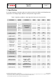
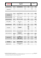
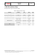
Data sheet BMA220 Page 9 4. Global memory map The memory map below shows all externally accessible data registers which are needed to operate BMA220.The left columns show the memory addresses. The columns in the middle depict the content of each register bit. The colors of the bits indicate whether they are read-only, write-only or read- and writable. The memory is volatile so that the writable content has to be rewritten after each power-on.
Data sheet BMA220 Page 10 4.1.2 Low-power mode configuration The BMA220 supports a low-power mode. In this low-power mode, the chip wakes up periodically, enables the interrupt controller and goes back to sleep if no interrupt has occurred. The procedure is the following: 1. Wake-up. 2. Enable analog front-end and convert acceleration data until the low-pass filters have settled. 3. Enable integrated interrupt controller and evaluate interrupt conditions.
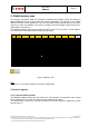
Data sheet BMA220 Page 11 4.1.3 Low-power mode dimensioning The power saving that can be achieved depends on the programmed sleep duration and the configured bandwidth. Figure 4 explains the power consumption in relation to the different ASIC states (sleep and awake phases). Figure 4: Sleep and awake phase If a low bandwidth is selected, the time required for filter settling might be the dominating time. Refer to table 2 for the appropriate dimensioning of the attainable current saving.
Data sheet BMA220 Page 12 4.1.5 Soft-reset The BMA220 can be put into a soft-reset state by performing a read from the soft-reset address. To bring the chip back into operation, another read must be performed from the same memory address. The reading returns value 0xFF if the system was in soft reset mode; otherwise it returns value 0x00. Please note that all internal configuration data programmed by the user will be lost. 4.1.6 Suspend mode The BMA220 can be put into a suspend mode e.g.
Data sheet BMA220 Page 13 4.2.2 Filter and bandwidth configuration The BMA220 has a digital filter that can be configured by setting the corresponding register bits filter_config[3:0] at address 0x10 (SPI) / 0x20 (I2C). For compatibility reasons the settings are defined based on BMA120. To always ensure an ideal cut off frequency of the filter the BMA220 is adjusting the sample rate automatically.
Data sheet BMA220 Page 14 4.3 Data registers 4.3.1 Acceleration data read-out The acceleration data can be read-out through addresses 0x02 (SPI) / 0x04 (I2C) through 0x04 (SPI) / 0x08 (I2C). The acceleration data is in 2’s complement according to the table below. An efficient way to read out the acceleration data in I²C or SPI mode is the burst-accesses. During such an access, the BMA220 automatically increments the read address after each byte.
Data sheet BMA220 Page 15 4.4 Interrupt control registers The BMA220 features a programmable interrupt controller that directly supports common mobile applications like tap sensing detection, orientation recognition and any-motion detection.
Data sheet BMA220 Page 16 5. Interrupt controllers The BMA220 integrates a programmable interrupt controller. It can be configured via SPI/I2C to monitor individual axes (X-, Y- and Z-axis) and check whether certain conditions apply (e.g. the acceleration on one axis exceeds a certain threshold). The interrupt controller of the BMA220 is capable of checking for certain conditions simultaneously.
Data sheet BMA220 Page 17 5.2 Supported types of interrupts The following interrupt modes are provided by the BMA220. Any-motion (slope) detection Tap/double-tap sensing Orientation recognition Low-g detection High-g detection Data-ready interrupt 5.
Data sheet BMA220 Page 18 5.4 Any-motion (slope) detection The any-motion detection uses the slope between two successive acceleration signals to detect changes in motion. It generates an interrupt when a preset threshold slope_th is exceeded. The threshold can be configured between 0 and the maximum acceleration value corresponding to the selected measurement range.
Data sheet BMA220 Page 19 acceleration acc(t0) acc(t0−1/(2*bw) time slope(t0)=acc(t0)−acc(t0−1/(2*bw)) slope slope_th time slope_dur slope_dur INT time Figure 6: Any-motion (slope) interrupt detection The following table shows the signals used in any-motion detection. After reset, a default value will be assigned to each register. BST-BMA220-DS003-08 | Revision 1.15 | August 2011 Bosch Sensortec © Bosch Sensortec GmbH reserves all rights even in the event of industrial property rights.
Data sheet BMA220 Page 20 Table 9: Control and status register for any motion detection en_slope_x en_slope_y en_slope_z Register Address (SPI) * 0x0D.5 0x0D.4 0x0D.3 slope_th 0x09[5:2] slope_dur 0x09[1:0] slope_filt 0x09.6 slope_int 0x0C.
Data sheet BMA220 Page 21 slope 1st TAP 2nd TAP tt_th time tap shock=50ms tap quiet = 30ms tt_dur = 12.
Data sheet BMA220 Page 22 5.5 Tap-sensing Tap sensing has the same functionality as a common laptop touch-pad. If 2 taps occur within a short time, a pre-defined action will be performed by the system. If time between 2 taps is too long or too short no action happens. When the serial interface is activated, tap sensing is enabled if any of the tap sensing enable register bits are set (en_tt_x, en_tt_y, en_tt_z). To disable the tap sensing interrupt, clear all the axis enable bits.
Data sheet BMA220 Page 23 Table 10: Control and status register for tap sensing Name Register Address (SPI) * en_tt_x en_tt_y en_tt_z 0x0D.2 0x0D.1 0x0D.0 tt_th 0x08[6:3] tt_dur 0x08[2:0] tt_filt 0x08.7 tip_en 0x0A.4 tt_int 0x0C.
Data sheet BMA220 Page 24 5.6 Orientation recognition The orientation recognition feature informs on an orientation change of the sensor with respect to the gravitational field vector g. The measured acceleration vector components with respect to the gravitational field look as follows.
Data sheet BMA220 portrait upright landscape left portrait upside down Page 25 landscape right portrait upright 2 1.5 1 0.5 0 0 45 90 135 180 225 270 315 360 -0.5 acc_y/acc_x -1 acc_x/sin(theta) -1.5 acc_y/sin(theta) -2 phi Figure 9: Orientation definition and interrupt thresholds with respect to the angle phi The criteria for portrait/landscape switching is fulfilled and the interrupt is generated when the threshold |acc_y/acc_x|=1 is crossed (i.e. 45°, 135°, 225°, 315°).
Data sheet BMA220 Page 26 The given specification is valid for an upright mounted PCB. In order to enable also horizontal mounting, x and z axis can be exchanged via the register orient_ex. The x-, y-, z-axis will keep right-hand principle after the exchange. When serial interface is active, orientation detection is enabled if the enable bit en_orient is set. To disable the orientation interrupt, clear the enable bit.
Data sheet BMA220 Page 27 5.7 Low-g detection For freefall detection, the absolute values of the acceleration data of all axes are observed (global criteria). A low-g situation is likely to occur when all axes fall below a lower threshold low_th. The interrupt will be generated if the measured acceleration falls below the threshold and stays below the hysteresis level low_th+low_hy for a minimum number of data points (low_dur).
Data sheet BMA220 Page 28 Table 12: Control and status register for low-g detection Name Register Address (SPI) * Description Number of bits Reset-value Low_th 0x06[7:4] define the low-g threshold level 1 LSB is 2*(LSB of acc_data) LOW_TH_NUM 4 Low_hy 0x07[7:6] define the low-g hysteresis level 1 LSB is 2*(LSB of acc_data) LOW_HY_NUM 2 LOW_TH_INIT “0100” LOW_HY_INI T “01” low_dur 0x07[5:0] en_low 0x0E.3 low_int 0x0C.
Data sheet BMA220 Page 29 5.8 High-g detection For indicating high-g events, an upper threshold can be programmed. The threshold high_th, the hysteresis high_hy and the duration high_dur are defined analogously to the low-g interrupt. The interrupt is generated if one of the three channels exceeds the threshold hight_th and does not fall below hysteresis level high_th-high_hy for minimum number of data points (high_dur).
Data sheet BMA220 Page 30 5.9 Data ready detection This interrupt provides the possibility of synchronously reading out data from the BMA220 without missing a single data point. The data update detection monitors the data_update signals for all axes. It generates an interrupt as soon as the acceleration values for all enabled axes have been updated. The signal en_x_channel, en_y_channel and en_z_channel are the enable signals for the data conversion from each axis accordingly.
Data sheet BMA220 Page 31 6. Operation modes Depending on the configuration the BMA220 is able to operate in two different types of modes General mode: A serial interface is active (SPI or I2C). Several interrupt engines may be activated in parallel. Through the serial interface, the external master (e.g. μC) can configure the interrupts of the BMA220 and read-out information about the current interrupt status. Dedicated mode: No serial interface is present.
Data sheet BMA220 Page 32 Table 15: Mode selection Mode SPI I²C Dedicated orientation Dedicated tap sensing Dedicated wakeup PS 0 1 SCK INT Z 0 Z 1 0 Z 1 1 Please note that the PS must be connected to the appropriate supply (or left floating) at start-up (reset). The “Z-detection” circuit will be turned off when a stable value at the PS pin has been detected. Thus, the dedicated modes can be only activated after reset.
Data sheet BMA220 Page 33 6.1 Dedicated Modes (μC-less / stand alone) After reset (POR, soft-reset or reset pin) the system monitors the pin PS (Protocol Select). If the pin is unconnected, an internal module detects the floating state and enables one of the dedicated modes depending on the other select pins (SCK, INT). There are three different dedicated modes: Orientation detection mode: only orientation interrupt detection is enabled.
Data sheet BMA220 Page 34 6.2 Digital interface modes The BMA220 supports two different digital interfaces (SPI and I²C). The currently active general interface is determined by the primary input PS. The configuration of interrupt engines is fully customizable via the defined digital interface. SPI Active Mode: The SPI interface is enabled while PS is externally connected to GND (logic ‘0’ detected).
Data sheet BMA220 Page 35 6.3 Low-power mode and suspend mode The BMA220 is optimized for low power consumption. Note: Simply switching-off of the power supplies (VDDD and/or VDDA) is not a defined low-power mode. The deactivation of VDDD while VDDA is active (or vice versa) is not recommended for permanent operation. With respect to the application it might be useful to switch-off VDDIO while VDDD and VDDA are active. This condition is supported and will lead to a reduction of current consumption.
Data sheet BMA220 Page 36 6.4 Mode transition via interface While the SPI or the I²C interfaces are active, transitions between the individual modes can be triggered via register accesses. 1. Low power: The BMA220 switches into low-power mode after setting the sleep_en register depicted in the memory map. While the BAA220 is in low-power mode, a period wake-up is performed (please refer to section 4.1.2). Normal mode operation is resumed after writing a ‘0’ to the sleep_en register.
Data sheet BMA220 Page 37 6.5 Self test mode The sensor features an on-chip self-test mode. The self test is realized by a physical deflection of the seismic mass due to an applied electrostatic force. Thus, it provides full testing of the complete signal evaluation path including the micromachined sensor structure and the evaluation ASIC. The self test mode can be activated individually for each axis by setting the the sbist register to the corresponding value (‘01’=x-axis, ‘10’=y-axis, ‘11’=z-axis).
Data sheet BMA220 Page 38 7. Interfaces The BMA220 can connect to the host system via three interfaces: SPI (3-wire, 4-wire) I²C Dedicated mode pins (for μC-less- or stand-alone operation, see section 6.1) In SPI and I²C mode, the BMA220 supports two commands: read and write. The ASIC can be entirely controlled through those commands. A detailed register to address mapping can be found in section 4.
Data sheet BMA220 Page 39 7.1 General digital interface description In general there are two common digital protocols selectable, the serial interfaces I²C and SPI. By default, SPI is used in the standard 4-wire configuration. The SPI interface may be configured by SW to operate in 3-wire interface mode, instead of standard 4-wire mode. The two serial interfaces are mapped onto the same pads. An external pin is needed to switch between the interfaces.
Data sheet BMA220 Page 40 7.2 SPI interface The SPI interface integrated in BMA220 is a slave SPI. 16-bit protocols are used for single byte reading and writing. Multiple bytes read-out is also possible. However, multiple bytes write is not supported. The BMA220 supports SPI only in SPI mode 3 (CPOL = 1, CPHA = 1). 4-wire SPI and 3-wire SPI are using same protocols. The communication starts with a read/write control bit followed by 7 bits address and at least 8 bits data.
Data sheet BMA220 Page 41 CSB SCK SDI R/W AD6 AD5 AD4 AD3 AD2 AD1 AD0 SDO DO7 DO6 DO5 DO4 DO3 DO2 DO1 DO0 tri-state Figure 16: 4-wire SPI read command Read command is completed in 16 clock cycles or in multiple of 8 in case of multiple byte read. In multiple-read cycle further blocks of 8 clock periods will be extended for each acknowledged data.
Data sheet BMA220 Page 42 Table 20: SPI Timing Parameter CSB lead time CSB lag time SDI setup time SDI hold time SDO delay time SCK period Symbol T_setup_csb T_hold_csb T_setup_sdi T_hold_sdi T_delay_sdo T_sck Condition CLoad ≤ 50pF Min 10 10 5 5 30 (MAX) 100 Units ns 3-wire SPI 3-wire SPI interface uses SDI pin for both data input and output. It can be invoked by setting the SPI3 register bit at address 0x0F. The write command for the 3-wire SPI is identical to the 4-wire SPI write command.
Data sheet BMA220 Page 43 7.3 I²C interface The I²C interface on board is a slave bus. Two signal lines SCL and SDA are used for communication. SDA is a bidirectional line used for sending and receiving data to/from the interface. SCL is the serial clock line used to synchronize the data. Both lines are connected to VDD via pull-up resistors. So the lines are pulled high when the bus is free. The lines are low only when any of the transmitters drives ‘0’.
Data sheet BMA220 Page 44 Table 21: I²C start/stop timing Parameter START hold time START setup time STOP setup time Symbol THDSTA TSUSTA TSUSTO Internal hold time THOLD_INT Clock to Data Out TVD_ACK Condition tf_SDA = 100 ns tf_SCL = 100 ns tf_SDA = 100 ns tf_SCL = 100 ns Min 0.6 0.6 0.6 Units μs 0.3 (MAX) 0.08 Acknowledge: Each byte of data transferred must be acknowledged. It is indicated by an acknowledge bit sent by the receiver.
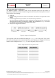
Data sheet BMA220 Page 45 SDA Thddat Tsudat SCK Data line stable, data valid Change of data allowed Figure 21: Waveform diagram for one bit transfer with I²C interface Table 22: I²C data transfer timing # Parameter Symbol Min Max Units 1 2 DATA hold time DATA setup time THDDAT TSUDAT 0 0.1 0.9 - μs The first byte of data transmitted after start condition contains the 7-bit address of I²C slave.
Data sheet BMA220 Page 46 I²C write command I²C write command only supports one byte writing. The protocol begins with start condition generated by master, followed by 7bits slave address and a write bit (R/W = 0). The slave sends an acknowledge bit (ACK = 0) and releases the bus. Then master sends the one byte register address (only the first 7bits are the valid address bits, the LSB shall be ignored).
Data sheet BMA220 Page 47 I²C read command I²C read command supports multiple bytes reading. A read command consists of a 1-byte I²C write phase followed by I²C read phase. The two I²C transmissions must be separated by a repeated start condition (Sr). The I²C write phase addresses the slave and sends the register address to be read. After slave acknowledges the transmission, master generates again a start condition and sends the slave address together with a read bit (R/W = 1).
Data sheet BMA220 Page 48 7.4 I²C watchdog timer In order to prevent the built-in I²C slave to lock-up the I²C bus, a watchdog timer (WDT) is introduced. The WDT observes internal I²C signals and resets the I²C interface if the bus is locked-up by the BMA220. The WDT observation period and WDT on/off can be configured through interface registers. Figure 24: WDT settings WDT_TO_en WDT_TO_sel WDT function 0 1 1 X 0 1 OFF 1 ms 10 ms 7.
Data sheet BMA220 Page 49 8. Pin-out and connecting diagram 8.
Data sheet BMA220 Page 50 8.2 Connecting diagrams Setup 1 I²C / SPI analog 1.8V SDO SDI PS SCK IO digital 1.62-3.6V 1.8V (top view) GND VDDA INT VDDIO VDDD C=100nF C=100nF C=100nF GND CAP0 BMA220 CSB GND Figure 28: BMA220 electrical connecting diagram setup option 1 Setup 2 VDDIO VDDD C=100nF PS analog + digital + IO 1.
Data sheet BMA220 Page 51 Setup 3 I²C / SPI VDDIO VDDD CSB GND BMA220 (top view) GND CAP0 SDI VDDA INT SDO PS analog 1.8V SCK digital + IO 1.8V C=100nF C=100nF GND Figure 30: BMA220 electrical connecting diagram setup option 3 Setup 4 I²C / SPI VDDIO VDDD C=100nF CSB BMA220 (top view) CAP0 SDI INT SDO PS analog + digital 1.8V SCK IO 1.62-3.6V GND GND VDDA C=100nF GND Figure 31: BMA220 electrical connecting diagram setup option 4 BST-BMA220-DS003-08 | Revision 1.
Data sheet BMA220 Page 52 In order to prevent noise on the supply pins VDDA, VDDD and VDDIO it is recommended to use lowleakage blocking capacitors with 100nF. The capacitors should be placed close to the respective pins as shown in figure 27.
Data sheet BMA220 Page 53 9. Package 9.1 Outline dimensions The sensor housing is a standard LGA package. It is compliant with JEDEC Standard MO-229 Type VGGD-3. Its dimensions are the following. Figure 32: Outline dimensions (in mm) BST-BMA220-DS003-08 | Revision 1.15 | August 2011 Bosch Sensortec © Bosch Sensortec GmbH reserves all rights even in the event of industrial property rights. We reserve all rights of disposal such as copying and passing on to third parties.
Data sheet BMA220 Page 54 9.2 Sensing axes orientation and polarity of the acceleration output If the sensor is accelerated in the indicated directions, the corresponding channel will deliver a positive acceleration signal (dynamic acceleration). If the sensor is at rest and the force of gravity is working along the indicated directions, the output of the corresponding channel will be negative (static acceleration).
Data sheet BMA220 Page 55 9.3 Landing pattern recommendation As for the design of the landing patterns, the following recommendations can be given: Figure 34: Landing patterns relative to the device pins, dimensions are in mm BST-BMA220-DS003-08 | Revision 1.15 | August 2011 Bosch Sensortec © Bosch Sensortec GmbH reserves all rights even in the event of industrial property rights. We reserve all rights of disposal such as copying and passing on to third parties.
Data sheet BMA220 Page 56 9.4 Marking 9.4.1 Mass production samples Labeling CCC TL Name Symbol Lot counter CCC Product number T Sub-con ID L Pin 1 identifier • Remark T=2 1 digit alphanumerical, code to identify sub-con and plant , L = A or L = U or L = P Figure 35: Marking of mass production samples 9.4.2 Engineering samples Labeling NWW CC Name Symbol Remark Eng. sample ID N Date code WW Engineering Samples are always marked with N = “e” calendar week Lot counter CC e.g. Eng.
Data sheet BMA220 Page 57 9.5 Moisture sensitivity level and soldering The moisture sensitivity level of the BMA220 sensors corresponds to JEDEC Level 1, see also IPC/JEDEC J-STD-020C "Joint Industry Standard: Moisture/Reflow Sensitivity Classification for non-hermetic Solid State Surface Mount Devices". IPC/JEDEC J-STD-033A "Joint Industry Standard: Handling, Packing, Shipping and Use of Moisture/Reflow Sensitive Surface Mount Devices".
Data sheet BMA220 Page 58 9.6 Tape and reel specification The BMA220 is shipped in a standard cardboard box. The box dimension for 1 reel is: L x W x H = 35cm x 35cm x 6cm BMA220 quantity: 10,000pcs per reel, please handle with care. Figure 38: reel dimensions in mm BST-BMA220-DS003-08 | Revision 1.15 | August 2011 Bosch Sensortec © Bosch Sensortec GmbH reserves all rights even in the event of industrial property rights.
Data sheet BMA220 Page 59 9.7 Orientation Processing direction Figure 39: BMA220 devices relative to tape 9.8 RoHS compliancy The BMA220 sensor meets the requirements of the EC restriction of hazardous substances (RoHS) directive, see also: Directive 2002/95/EC of the European Parliament and of the Council of 27 January 2003 on the restriction of the use of certain hazardous substances in electrical and electronic equipment. 9.
Data sheet BMA220 Page 60 9.11 Handling instruction Micromechanical sensors are designed to sense acceleration with high accuracy even at low amplitudes and contain highly sensitive structures inside the sensor element. The MEMS sensor can tolerate mechanical shocks up to several thousand g's. However, these limits might be exceeded in conditions with extreme shock loads such as e.g. hammer blow on or next to the sensor, dropping of the sensor onto hard surfaces etc.
Data sheet BMA220 Page 61 10. Legal disclaimer 10.1 Engineering samples Engineering Samples are marked with an asterisk (*) or (e) or (E). Samples may vary from the valid technical specifications of the product series contained in this data sheet. They are therefore not intended or fit for resale to third parties or for use in end products. Their sole purpose is internal client testing. The testing of an engineering sample may in no way replace the testing of a product series.
Data sheet BMA220 Page 62 11. Document history and modifications Rev. No 0.9 0.91 0.92 Chapter All All 1 2 9.1 9.2 0.93 9.2 10.6 1 2 4 4.1.5 4.1.6 5.5 6 6.3. 7 ex 8.3 new 7.3 ex 8.5 new 7.5 ex 9.1 new 8.1 ex 9.2 new 8.2 ex 9.2 new 8.2 ex 10.6 new 9.6 ex 10.8 new 9.8 1.00 1 4 4.1.2 4.1.3 6.3 7.2 All 1.01 1.05 Title 1 9.4.1 4.1.2, 4.1.
Data sheet BMA220 1.10 1.15 6.1, 7.2 4.3.1 7.3 7.2 7.3 Page 63 Active “1” level = VDDIO Update table 7 Update figures 22 and 23 Comment on SPI mode 3 Updated 2011-04-13 2011-08-23 Bosch Sensortec GmbH Gerhard-Kindler-Strasse 8 72770 Reutlingen / Germany contact@bosch-sensortec.com www.bosch-sensortec.com Modifications reserved | Printed in Germany Specifications subject to change without notice Document number: BST-BMA220-DS003-08 Revision_1.15_082011 BST-BMA220-DS003-08 | Revision 1.