Photobeam 5000 ISC-FPB1-W60QS, ISC-FPB1-W120QS, ISC-FPB1-W200QS en Installation and Operation Guide
Photobeam 5000 Table of Contents | en 3 Table of contents 1 Introduction 4 1.1 About documentation 4 1.2 Bosch Security Systems, Inc 4 2 System overview 5 2.1 Features 5 2.2 Photobeam overview 6 2.3 Console overview 7 2.4 Transmitter/receiver dimensions 8 3 Installation 9 3.1 Beam spread 9 3.2 Pole mount installation 10 3.3 Wall mount installation 12 4 Wiring 13 4.1 Terminal strip overview 13 4.2 Wiring distance 14 4.
1 en | Introduction Photobeam 5000 Introduction This document contains information that a trained installer needs to install the Photobeam 5000 quad-beam photoelectric detector contained inside the packaging. 1.1 About documentation Copyright This document is the intellectual property of Bosch Security Systems, Inc. and is protected by copyright. All rights reserved.
Photobeam 5000 2 System overview | en 5 System overview The ISC-FPB1-W60QS, ISC-FPB1-W120QS and ISC-FPB1-W200QS are quad-beam photoelectric detectors designed for indoor and outdoor applications. Consisting of a separate transmitter and receiver, an alarm is activated when a person passes through all four beams. Combination of features and adjustable parameters allow for better catch performance, lower false alarm rates and reduced effects of environmental disturbances. 2.
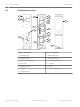
2.2 en | System overview Photobeam 5000 Photobeam overview 2 7 6 8 1 9 12 10 5 11 4 10 9 1 7 8 3 13 Figure 2.1: Photobeam components overview Callout ー Description Callout ー Description 1 ー Mounting holes 8 ー Optical alignment 2 ー Mounting plate 9 ー Vertical adjustment 3 ー Device securing screws 10 ー Horizontal adjustment 4 ー Wire entry 11 ー Console 5 ー Wiring terminals 12 ー Cover 6 ー Detector 13 ー Cover securing screws 7 ー Optical module 2016.02 | 03 | F.01U.305.
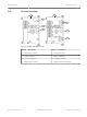
Photobeam 5000 2.3 System overview | en 7 Console overview 5 1 2 6 3 4 7 8 Figure 2.2: Console components overview Callout ー Description Callout ー Description 1 ー Transmitter console 5 ー Receiver console 2 ー Power Indicator 6 ー Status Indicators 3 ー Function switches 7 ー Sensitivity control 4 ー Beam Power Control 8 ー Alignment check terminals Bosch Security Systems, Inc. Installation and Operation Guide 2016.02 | 03 | F.01U.305.
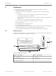
Photobeam 5000 Transmitter/receiver dimensions 103 mm (4.0 in) (3.03 in) 77.1 mm 96 mm (3.77 in) 39 mm 39.7 mm (1.5 in) (1.56 in) 2.4 en | System overview 398 mm (15.66 in) 244 mm (9.60 in) 337.7 mm (13.29 in) 3 56 mm (2.20 in) 220 mm (8.66 in) 8 4 1 2 19.3 mm (0.75 in) Figure 2.3: Transmitter/receiver dimensions Callout ﹘ Description Callout ﹘ Description 1 ー Knockout wire entrance 3 ー Center of the Upper Beam 2 ー Center of the Lower Beam 4 ー Wire entrance 2016.02 | 03 | F.01U.305.
Photobeam 5000 3 Installation | en 9 Installation Prior to installing the devices, please review the installation considerations below: – Install in an area that is clear of objects – Install the transmitter/receiver within the maximum protection range of the model – Do not install: – Receivers into intense sources of light (for example, rising and setting sun) – On movable surfaces subject to vibrations – Detectors where immersion to water, corrosive liquids, or exposure to high levels of dus
en | Installation Photobeam 5000 Distance, horizontal and vertical spread values: (A) / (B) / (C) 3.2 Metric Imperial unit 20 m / 0.5 m / 0.8 m 65 ft / 1.6 ft / 2.6 ft 40 m / 1.0 m /1.3 m 13.1 ft / 3.2 ft / 4.2 ft 60 m / 1.5m / 1.8 m 196 ft / 4.9 ft / 5.9 ft 80 m / 2.0 m / 2.2 m 262 ft / 6.5 ft / 7.2 ft 100 m / 2.5 m / 2.7 m 328 ft / 8.2 ft / 8.8 ft 120 m / 3.0 m / 3.2 m 393 ft / 9.8 ft / 10.4 ft 140 m / 3.5 m / 3.7 m 459 ft / 11.4 ft / 12.1 ft 160 m / 4.0 m / 4.2 m 524 ft / 13.
Installation | en Photobeam 5000 1 11 2 3 Figure 3.3: Attaching the mounting bracket Callout ﹘ Description 1 ー Mounting hardware 2 ー Mounting plate 3 ー Clamping screws (short) Attaching the mounting plate: 1. Attach the mounting plate to the poles using the U-clamps. 2. Use the U-clamps and clamping screws to attach the mounting plate firmly to the poles. 2 3 1 4 Figure 3.
en | Installation Photobeam 5000 Caution! ! 3.3 Ensure that the pole mount installation is secure and stable. Failure to do so may result in personal injury, or damage the device. Wall mount installation Installing the transmitter and receiver: 1. Remove the cover and mounting plate from the transmitter. 2. Route the wire through the mounting plate wire entry if the wire is routed through a wall opening.
Photobeam 5000 Wiring | en 13 Wiring 4 Refer to Terminal strip below for transmitter/receiver terminal locations. Use duct pipes for outdoor wiring. Do not use aerial wiring. Caution! ! Only apply power after all electrical connections are completed and inspected. Notice! Tamper and EDC terminals should be connected to a 24-hour supervisory loop Notice! Power is to be provided by a UL Listed burglar alarm power supply or burglar alarm control panel.
4.2 en | Wiring Photobeam 5000 Wiring distance Refer to the table to determine the minimum wire gauge for a single sensor system (one transmitter and one receiver). The distances specified are between the power source and the last (farthest) unit on the single wire run. For multiple detector configurations, divide the wire distance in the table by the number of systems in the configuration (1 system = 1 transmitter and 1 receiver).
Photobeam 5000 Wiring | en 15 1 5 4 2 3 4 Figure 4.2: Wiring for one set on the run Callout ﹘ Description Callout ﹘ Description 1 ー Power output 4 ー Control panel 2 ー Transmitter 5 ー Alarm input. The COM and NC terminals on the unit are the outputs, they connect to a control panel input. 3 ー Receiver 1 5 4 3 3 2 2 Figure 4.3: Wiring for two sets on a single run Callout ﹘ Description Callout ﹘ Description 1 ー Power output 4 ー Control panel 2 ー Transmitter 5 ー Alarm input.
5 en | Special features Photobeam 5000 Special features Refer to the following for sensitivity adjustments. 5.1 Level LED The Level LED shows the beams energy level received during alignment. As more beam energy is received, the illumination time shortens as follows: ON => OFF once => OFF twice => OFF three times => Flashing => ON three times => ON twice => ON once => OFF. When the LED turns off, the alignment is complete.
Photobeam 5000 Special features | en 17 Notice! The EDC feature was not investigated by Underwriters Laboratories (UL). 5.3 Beam interruption time The beam interruption time defines the amount of time an intruder must spend in the beam path before an alarm is generated. For instance, if the interruption time is set at 100 ms, the detector only generates an alarm if the beams are blocked for more than 100 ms. Notice! For UL applications, do not set the interrupt time above 75 ms. 5.
6 en | Setup Photobeam 5000 Setup Turn the Bypass switch on to activate the bypass feature. 2 1 3 Figure 6.1: Receiver Bypass switch Callout ー Description 1 ー Receiver 2 ー Bypass switch (switch 1) 3 ー Sensitivity control Interruption time Turn the sensitivity control on the receiver clockwise to reduce sensitivity and counterclockwise to increase sensitivity. 1 2 3 5 4 Figure 6.
Photobeam 5000 Setup | en 19 Model Volume setting of beam power control ISC-FPB1- volume 20 30 40 50 55 60 range <20 m 20-30 m 30-40 m 40-50 m 50-55 m 55-60 m (65 ft) (65-98 ft) (98-131 (131-164 (164-180 (180-196 ft) ft) ft) ft) 120 W60QS ISC-FPB1W120QS volume 40 60 80 100 110 range <40 m 40-60 m 60-80 m 80-100 m 100-110 m 110-120 m (131 ft) (131-196 ISC-FPB1W200QS (196-262 (262-328 (328-360 (360-393 ft) ft) ft) ft) ft) 160 180 200 volume 60 100 13
7 en | Optical alignment Photobeam 5000 Optical alignment Perform the following to align the detector. 7.1 Level LED - alignment of the Upper Beam Perform the following to align the upper beam. Aligning of the upper bean: 1. Turn on the transmitter Function switch 1 (Upper Beam). The monitor LED flashes (5 times/sec). 2. Turn on the receiver Function switch 2 (Level Check) of the receiver. 3.
Photobeam 5000 Optical alignment | en 2. 21 Turn on the receiver Function switch 2 (Level Check). Follow steps 3 and 4 as listed in the Level LED - alignment of the Upper Beam, page 20. If the LED turns off, alignment is complete. 1 Figure 7.2: LED alignment Callout ー Description 1 ー Receiver LED console 7.3 Volt meter alignment Insert the volt meter leads into the alignment check terminals of the receiver to check voltage. If the value is 3.0 V or higher, the adjustment is completed.
8 en | Operational check Photobeam 5000 Operational check Perform the following to test the overall operation of the system. Walk test Testing the alarm signal: 1. Walk along the beam path near the transmitter and receiver in a pattern crossing the beam signal in three different areas as depicted in the illustration below (callout’s 2, 4 and 5 – Walk test crossing location), and check the alarm LEDs. Refer to the Walk test illustration below. The alarm LED turns on each time you cross the beam path.
Photobeam 5000 9 Troubleshooting | en 23 Troubleshooting In case of trouble, verify the following: – Transmitter and receiver power supply voltage is between 10.
10 en | Certifications Photobeam 5000 Certifications Region Agency Certification US UL UL 639 Intrusion Detection Units and Systems Europe CE Hereby, Bosch, declares that this transmitter is in compliance with the essential requirements and other relevant provisions of Directive 1999/5/EC 2016.02 | 03 | F.01U.305.910 Installation and Operation Guide Bosch Security Systems, Inc.
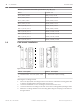
Photobeam 5000 11 Specifications | en 25 Specifications Product Name Photoelectric Detector Model ISC-FPB1-W60QS ISC-FPB1-W120QS ISC-FPB1-W200QS Outdoor range 60 m (196 ft) 120 m (393 ft) 200 m (656 ft) Transmitter current draw 20 mA 25 mA 30 mA Receiver current draw 70 mA Power 10.5VDC – 28 VDC Optical alignment +/- 90° Horizontally,+/-10° vertically Alarm output – Form C relay (COM, NC, NO) (dry-contact) – Duration - 2 sec – Contact capacity – 30 VDC, 0.
Bosch Security Systems, Inc. 130 Perinton Parkway Fairport, NY 14450 USA www.boschsecurity.com © Bosch Security Systems, Inc., 2016 Bosch Sicherheitssysteme GmbH Robert-Bosch-Ring 5 85630 Grasbrunn Germany www.boschsecurity.