
Installation Manual


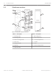

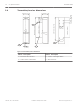


Table Of Contents

Photobeam overview
2
1
1
4
5
6
7
8
9
10
11
10
9
7
8
3
13
12
Figure 2.1: Photobeam components overview
Callout ー Description
Callout ー Description
1 ー Mounting holes 8 ー Optical alignment
2 ー Mounting plate 9 ー Vertical adjustment
3 ー Device securing screws 10 ー Horizontal adjustment
4 ー Wire entry 11 ー Console
5 ー Wiring terminals 12 ー Cover
6 ー Detector 13 ー Cover securing screws
7 ー Optical module
2.2
6 en | System overview Photobeam 5000
2015.01 | 02 | F.01U.303.478 Installation and Operation Guide Bosch Security Systems, Inc.