
Installation Manual


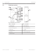

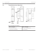


Table Of Contents

Distance, horizontal and vertical spread values: (A) / (B) / (C)
Metric Imperial unit
20 m / 0.5 m / 0.8 m 65 ft / 1.6 ft / 2.6 ft
40 m / 1.0 m /1.3 m 13.1 ft / 3.2 ft / 4.2 ft
60 m / 1.5m / 1.8 m 196 ft / 4.9 ft / 5.9 ft
80 m / 2.0 m / 2.2 m 262 ft / 6.5 ft / 7.2 ft
100 m / 2.5 m / 2.7 m 328 ft / 8.2 ft / 8.8 ft
120 m / 3.0 m / 3.2 m 393 ft / 9.8 ft / 10.4 ft
140 m / 3.5 m / 3.7 m 459 ft / 11.4 ft / 12.1 ft
160 m / 4.0 m / 4.2 m 524 ft / 13.1 ft / 13.7 ft
180 m / 4.5 m / 4.7 m 590 ft / 14.7 ft / 15.4 ft
200 m / 5.0 m / 5.2 m 656 ft / 16.4 ft / 17.0 ft
Pole mount installation
1
2
Figure 3.2: Pole mounting view
Callout ﹘ Description
Callout ﹘ Description
1 ー Diameter 38.0 – 42.7 mm (1.50 – 1.68
in)
2 ー Back-to-back pole mounting
Attaching the mounting bracket:
1. Choose an appropriate mounting location for the devices. Install the mounting poles with
a clear line-of-sight between the transmitter and receiver.
2. Loosen the transmitter’s cover mounting screw and remove the cover.
3. Loosen the two base mounting screws and remove the mounting plate by sliding it down.
4. Attach the mounting hardware to the mounting plate using the clamping screws. Refer to
the figure below.
3.2
10 en | Installation Photobeam 5000
2015.01 | 02 | F.01U.303.478 Installation and Operation Guide Bosch Security Systems, Inc.