Photobeam 5000 ISC-FPB1-W60QF, ISC-FPB1-W120QF, ISC-FPB1-W200QF en Installation and Operation Guide
Photobeam 5000 Table of Contents | en 3 Table of contents 1 Introduction 4 1.1 About documentation 4 1.2 Bosch Security Systems, Inc 4 2 System overview 5 2.1 Features 5 2.2 Photobeam overview 6 2.3 Console overview 7 2.4 Transmitter/receiver dimensions 8 3 Installation 9 3.1 Beam spread 9 3.2 Pole mount installation 10 3.3 Wall mount installation 12 4 Wiring 13 4.1 Terminal strip overview 13 4.2 Wiring distance 14 4.
1 en | Introduction Photobeam 5000 Introduction This document contains information that a trained installer needs to install the Photobeam 5000 quad-beam photoelectric detector contained inside the packaging. 1.1 About documentation Copyright This document is the intellectual property of Bosch Security Systems, Inc. and is protected by copyright. All rights reserved.
Photobeam 5000 2 System overview | en 5 System overview The ISC-FPB1-W60QF, ISC-FPB1-W120QF, and ISC-FPB1-W200QF are quad-beam photoelectric detectors designed for indoor and outdoor applications. Consisting of a separate transmitter and receiver, an alarm is activated when a person passes through the beams. Combination of features and adjustable parameters allow for better catch performance, lower false alarm rates, and reduced effects of environmental disturbances. 2.
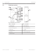
2.2 en | System overview Photobeam 5000 Photobeam overview 2 6 7 8 1 9 12 10 5 11 4 10 9 1 3 8 7 13 Figure 2.1: Photobeam components overview Callout ー Description Callout ー Description 1 ー Mounting holes 8 ー Optical alignment 2 ー Mounting plate 9 ー Vertical adjustment 3 ー Device securing screws 10 ー Horizontal adjustment 4 ー Wire entry 11 ー Console 5 ー Wiring terminals 12 ー Cover 6 ー Detector 13 ー Cover securing screws 7 ー Optical module 2015.01 | 02 | F.01U.303.
Photobeam 5000 2.3 System overview | en 7 Console overview 5 1 2 6 3 4 7 8 9 Figure 2.2: Console components overview Callout ー Description Callout ー Description 1 ー Transmitter console 6 ー Status indicators 2 ー Power indicator 7 ー Sensitivity control 3 ー Function switches 8 ー ALIGNMENT CHECK TERMINALS 4 ー BEAM POWER CONTROL 9 ー HIGH DENSITY terminals 5 ー Receiver console Bosch Security Systems, Inc. Installation and Operation Guide 2015.01 | 02 | F.01U.303.
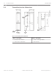
Photobeam 5000 Transmitter/receiver dimensions 103 mm (4.0 in) (3.03 in) 77.1 mm 96 mm (3.77 in) 39 mm 39.7 mm (1.5 in) (1.56 in) 2.4 en | System overview 398 mm (15.66 in) 244 mm (9.60 in) 337.7 mm (13.29 in) 3 56 mm (2.20 in) 220 mm (8.66 in) 8 4 1 2 19.3 mm (0.75 in) Figure 2.3: Transmitter/receiver dimensions Callout ﹘ Description Callout ﹘ Description 1 ー Knockout wire entrance 3 ー Center of the Upper Beam 2 ー Center of the Lower Beam 4 ー Wire entrance 2015.01 | 02 | F.01U.303.
Photobeam 5000 3 Installation | en 9 Installation Prior to installing the devices, please review the installation considerations below: – Install in an area that is clear of objects – Install the transmitter/receiver within the maximum protection range of the model – Do not install: – Receivers into intense sources of light (for example, rising and setting sun) – On movable surfaces subject to vibrations – Detectors where immersion to water, corrosive liquids, or exposure to high levels of dus
en | Installation Photobeam 5000 Distance, horizontal and vertical spread values: (A) / (B) / (C) 3.2 Metric Imperial unit 20 m / 0.5 m / 0.8 m 65 ft / 1.6 ft / 2.6 ft 40 m / 1.0 m /1.3 m 13.1 ft / 3.2 ft / 4.2 ft 60 m / 1.5m / 1.8 m 196 ft / 4.9 ft / 5.9 ft 80 m / 2.0 m / 2.2 m 262 ft / 6.5 ft / 7.2 ft 100 m / 2.5 m / 2.7 m 328 ft / 8.2 ft / 8.8 ft 120 m / 3.0 m / 3.2 m 393 ft / 9.8 ft / 10.4 ft 140 m / 3.5 m / 3.7 m 459 ft / 11.4 ft / 12.1 ft 160 m / 4.0 m / 4.2 m 524 ft / 13.
Installation | en Photobeam 5000 1 11 2 3 Figure 3.3: Attaching the mounting bracket Callout ﹘ Description 1 ー Mounting hardware 2 ー Mounting plate 3 ー Clamping screws (short) Attaching the mounting plate: 1. Attach the mounting plate to the poles using the U-clamps. 2. Use the U-clamps and clamping screws to attach the mounting plate firmly to the poles. 2 3 1 4 Figure 3.
en | Installation Photobeam 5000 Caution! ! 3.3 Ensure that the pole mount installation is secure and stable. Failure to do so may result in personal injury, or damage the device. Wall mount installation Installing the transmitter and receiver: 1. Remove the cover and mounting plate from the transmitter. 2. Route the wire through the mounting plate wire entry if the wire is routed through a wall opening.
Photobeam 5000 Wiring | en 13 Wiring 4 Refer to Terminal strip below for transmitter/receiver terminal locations. Use duct pipes for outdoor wiring. Do not use aerial wiring. Caution! ! Complete all electrical connections and inspect them prior to applying power. Notice! Tamper and EDC terminals should be connected to a 24-hour supervisory loop Notice! Power is to be provided by a UL Listed burglar alarm power supply or burglar alarm control panel.
4.2 en | Wiring Photobeam 5000 Wiring distance Refer to the table to determine the minimum wire gauge for a single sensor system (one transmitter and one receiver). The distances specified are between the power source and the last (farthest) unit on the single wire run. For multiple detector configurations, divide the wire distance in the table by the number of systems in the configuration (1 system = 1 transmitter and 1 receiver).
Photobeam 5000 Wiring | en 15 1 5 4 2 3 4 Figure 4.2: Wiring for one set on the run Callout ﹘ Description Callout ﹘ Description 1 ー Power output 4 ー Control panel 2 ー Transmitter 5 ー Alarm input. The COM and NC terminals on the unit are the outputs, they connect to a control panel input. 3 ー Receiver 1 5 4 3 3 2 2 Figure 4.3: Wiring for two sets on a single run Callout ﹘ Description Callout ﹘ Description 1 ー Power output 4 ー Control panel 2 ー Transmitter 5 ー Alarm input.
5 en | Special features Photobeam 5000 Special features Refer to the following for sensitivity adjustments. 5.1 Selectable beams Crosstalk occurs when multiple beams are stacked or when used in long distances which might cause a missed alarm (no catch). The devices are equipped with 8 different selectable beam channels (2 Groups and 4 Channels) to prevent crosstalking.
Photobeam 5000 Special features | en Switch Condition 17 Description When both optical The alarm LED turns on and an alarm signal is generated. modules are blocked for EDC LED turns on and EDC output activates. 3 or more seconds: On When poor The EDC LED turns on and the EDC output activates. environmental conditions Alarm LED turns on after further loss of beam energy but present: does not generate an alarm signal. When either optical The EDC LED turns on and provides a EDC signal.
en | Special features Photobeam 5000 catch). Beam Power level set to greater than the installation range may also cause cross-talk with other devices in the line of sight of the transmitter. The Beam Power Control adjusts the amount of beam energy for optimal range. 1 2 Figure 5.1: Detection range Callout ﹘ Description 1 ー Short range 2 ー Maximum detection range 5.
Special features | en Photobeam 5000 19 1 2 3 4 2 3 5 2 3 Figure 5.2: High density synchro wiring Callout ﹘ Description 1 ー Receiver 1 2 ー Receiver IN connections 3 ー Receiver OUT connections 4 ー Receiver 2 5 ー Receiver 3 Bosch Security Systems, Inc. Installation and Operation Guide 2015.01 | 02 | F.01U.303.
en | Special features Photobeam 5000 2 4 1 3 4 Figure 5.3: High density configuration Callout ﹘ Description 1 ー Transmitters (1, 2, and 3) 2 ー Intruder (breaking the beams of transmitter 1 and 2) 3 ー Receivers (1, 2, and 3) 4 ー OUT/IN connections 2015.01 | 02 | F.01U.303.478 Installation and Operation Guide Bosch Security Systems, Inc.
Photobeam 5000 6 Setup | en 21 Setup Turn the Bypass switch on to activate the bypass feature. 1 2 3 Figure 6.
en | Setup Photobeam 5000 1 2 3 4 5 6 Figure 6.2: Interruption time Callout ﹘ Description Callout ﹘ Description 1 ー 40 ms running 4 ー 300 ms normal walking 2 ー 100 ms jogging 5 ー 400 ms slow walking 3 ー 200 ms fast walking 6 ー 500 ms slow moving Beam power control Turn the Beam Power Control on the transmitter clockwise to increase beam power. Turn counter-clockwise to decrease beam power. Refer to table below. 2015.01 | 02 | F.01U.303.
Photobeam 5000 Setup | en Model Volume setting of beam power control (outdoors) ISC-FPB1- volume 20 30 40 50 55 60 range <20 m 20-30 m 30-40 m 40-50 m 50-55 m 55-60 m (65 ft) (65-98 ft) (98-131 ft) (131-164 ft) (164-180 ft) (180-196 ft) volume 40 60 80 100 110 120 range <40 m 40-60 m 60-80 m 80-100 m 100-110 m 110-120 m (131 ft) (131-196 ft) (196-262 ft) (262-328 ft) (328-360 ft) (360-393 ft) volume 60 100 130 160 180 200 range <60 m 60-100 m 100-130 m
en | Setup Photobeam 5000 1 2 3 Figure 6.3: Beam switch Callout ﹘ Description Callout ﹘ Description 1 ー Transmitter 3 ー Beam power control 2 ー Beam switch 2015.01 | 02 | F.01U.303.478 Installation and Operation Guide Bosch Security Systems, Inc.
Photobeam 5000 7 Installing multiple sets (stacking) | en 25 Installing multiple sets (stacking) This section describes the positioning of photobeam sets as well as several examples of how they are stacked. Depending on your installation environment, you can install a single or up to a four-level stack for maximum coverage. The term ”set“ describes one transmitter and one receiver pairing. The term “crosstalk” is a type of interference.
en | Installing multiple sets (stacking) Photobeam 5000 2 1 3 Figure 7.1: Transmitter Callout ﹘ Description 1 ﹘ Switches 1, 2, and 3 (Switch 1 determines Group A or Group B selection. Switches 2 and 3 determine channel assignments.) 2 ﹘ Transmitter 3 ﹘ Switch 4 (not used) 2 1 Figure 7.2: Receiver Callout ﹘ Description 1 ﹘ Switches 1, 2, and 3 (Switch 1 determines Group A or Group B selection. Switches 2 and 3 determine channel assignments.
Photobeam 5000 Installing multiple sets (stacking) | en Group Switch No. 1 A OFF B ON 27 Table 7.1: Group selection Application The use of the beam Group A/Group B selection is best illustrated below. R 1 T T R 2 1 2 R 1 4 T T 2 2 R 1 3 Figure 7.
en | Installing multiple sets (stacking) Photobeam 5000 In a multi-stack configuration, it is possible to have a stack or a row of four-beam sets assigned to Group A, with each stack also being assigned to a specific channel, channel M (Master), 1, 2, or 3. A similar configuration is possible with a multiple stack configuration assigned to Group B. Channels 1, 2, and 3 emit beams only when Channel M (Master) is active.
Photobeam 5000 Installing multiple sets (stacking) | en 29 Synchro wiring 7.3 Use synchronized (abbreviated “synchro”) wires when installing two or more sets in the same group by using the SYNCHRO terminal on each transmitter. Synchro wires allow each transmitter’s frequency to be synchronized at the same starting point to eliminate false emissions to the receiver. Synchro wires are not required between the receivers.
en | Installing multiple sets (stacking) 7.4 Photobeam 5000 Stacking examples Photobeam sets combined together form a stack. A stack is similar to a row in that you can install up to four rows (stacks) of photobeams when securing a perimeter, or area. In the following sections, four stacking examples are shown with brief descriptions as to why you might install a stack configuration. 7.4.1 Single stacking Refer to the following graphic below for a single stack example.
Photobeam 5000 Installing multiple sets (stacking) | en 3 4 R T 12 4 12 3 T R R 12 3 T T 31 R 2 1 7 12 6 5 Figure 7.
en | Installing multiple sets (stacking) Photobeam 5000 4 5 R T 12 5 12 4 T R R 12 4 T T R 3 2 1 8 12 7 6 Figure 7.
Installing multiple sets (stacking) | en Photobeam 5000 33 Stacking in long distance (quadruple stack) 5 R 6 T 12 6 12 5 T R R 12 5 T T R 4 3 2 1 9 12 8 7 Callout ﹘ Description 1 ﹘ Fourth stack assigned to Channel 3 2 ﹘ Third stack assigned to Channel 2 3 ﹘ Second stack assigned to Channel 1 4 ﹘ First stack assigned to Channel M 5 ﹘ Receiver 6 ﹘ Transmitter 7 ﹘ Group B transmitter/receiver pairs 8 ﹘ Synchro wiring 9 ﹘ Group A transmitter/receiver pairs Application Use a quadruple stac
en | Installing multiple sets (stacking) – 2015.01 | 02 | F.01U.303.478 Photobeam 5000 Use Synchro wiring as illustrated in the graphic above. Installation and Operation Guide Bosch Security Systems, Inc.
Photobeam 5000 8 Optical alignment | en 35 Optical alignment Perform the following to align the detector. 8.1 Level LED – alignment of the Upper Beam Perform the following to align the upper beam. Aligning of the upper beam: 1. Turn on the receiver Function switch 6. The monitor LED flashes (5 times/sec). 2. Look into the scope at the center of the lens from a 10-15 cm (4-5 in) distance, adjust the horizontal direction by rotating the turntable and the horizontal adjustment screw.
en | Optical alignment Photobeam 5000 1. Turn off the transmitter Function switch 6. 2. Follow steps 2 and 3 as listed in the Level LED – alignment of the Upper Beam procedure. If LED turns off, alignment is complete. 1 Figure 8.2: Level LED Callout ﹘ Description 1 ー Receiver LED console Notice! Turn on Function switches 1 and 2 of the transmitter after finishing the alignment to verify the monitor LEDs light up once every 3 seconds. 8.
Photobeam 5000 Optical alignment | en 37 Notice! Turn on Function switches 1 and 2 of the transmitter after finishing the alignment to verify the monitor LEDs light up once every 3 seconds. Bosch Security Systems, Inc. Installation and Operation Guide 2015.01 | 02 | F.01U.303.
9 en | Operational check Photobeam 5000 Operational check Perform the following to test the overall operation of the system. Walk test Testing the alarm signal: 1. Walk along the beam path near the transmitter and receiver in a pattern crossing the beam signal in three different areas as depicted in the illustration below (callout’s 2, 4 and 5 – Walk test crossing location), and check the alarm LEDs. Refer to the Walk test illustration below. The alarm LED turns on each time you cross the beam path.
Photobeam 5000 10 Troubleshooting | en 39 Troubleshooting In case of trouble, verify the following: – Transmitter and receiver power supply voltage is between 10.
11 en | Certifications Photobeam 5000 Certifications Region Agency Certification US UL UL 639 Intrusion Detection Units and Systems Europe CE Hereby, Bosch, declares that this transmitter is in compliance with the essential requirements and other relevant provisions of Directive 1999/5/EC 2015.01 | 02 | F.01U.303.478 Installation and Operation Guide Bosch Security Systems, Inc.
Photobeam 5000 12 Specifications | en 41 Specifications Product Name Photoelectric Detector Model ISC-FPB1-W60QF ISC-FPB1-W120QF ISC-FPB1-W200QF Max. outdoor range 60 m (196 ft) 120 m (393 ft) 200 m (656 ft) Max. indoor range 120 m (393 ft) 240 m (787 ft) 400 m (1312 ft) Transmitter current draw 20 mA 24 mA 28 mA Receiver current draw 100 mA Power 10.
Bosch Security Systems, Inc. 130 Perinton Parkway Fairport, NY 14450 USA www.boschsecurity.com © Bosch Security Systems, Inc.