
Installation Manual


Page 6
Before you begin
Tools and Parts Needed
• Measuring tape
• Pencil
• Phillips screwdriver (Posidrive) #2
• Drill with the following bits:
5
⁄16” (7.9 mm) and
3
⁄8”
(9.5 mm)
• Spirit-level
• Aluminum tape (DO NOT use insulating tape)
• Exhaustchannel(congurationdependsonthe
installation situation)
• Additional sheet metal screws (if necessary for
installation of the exhaust air duct)
• Saw
• Home power supply cable
• 1/2” (13 mm) UL listed or CSA approved strain relief
• Three UL Listed wire connectors
Parts Included
• Extractorhoodwithfan,back-pressureap
• Lamps, already installed
• Metalgreaselter
• Flue duct
• Drill template
• 1xanglebracketfortheueduct
• Installation manual and instructions for use
• 6x screws, 5x45 mm
• 12x screws, 4.2x8 mm
• 2x washers, 6.4x18 mm
• 2x hollow wall plugs, 8x40 mm
• 4x hollow wall plugs, 10x50 mm
• Torx adapter, 10 & 20
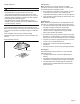
NOTE:Carefullyremovetheprotectivelmfromtheduct
cover and hood assembly prior to the start of the installation.
Use one hand to maintain the assembly/duct cover steady
whiletheotherhandremovestheprotectivelm.
Use gloves at all time.
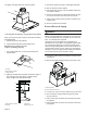
Appliance Dimensions
30" (762 mm)
36" (914 mm)
A
19
11
/
16
"
(500 mm)
7
7
/
8
"
(200 mm)
10
3
/
4
"
(273 mm)
13
3
/
16
"
(335 mm)
5¾"
(146 mm)
A Only for circulating-air mode:
*Max. 43
1
⁄2" (1106 mm)
*Min. 29" (734 mm)
Only for ducted operation:
*Max. 39
1
⁄2" (1006 mm)
*Min. 25" (633 mm)