
User Manual


20 | English
1 609 92A 2CC | (30.9.16) Bosch Power Tools
Assembly
Mounting the Protective Devices
Before any work on the machine itself, pull the mains
plug.
Note: After breakage of the grinding disc during operation or
damage to the holding fixtures on the protection guard/power
tool, the machine must promptly be sent to an after-sales ser-
vice agent for maintenance. For addresses, see section “Af-
ter-sales Service and Application Service”.
Protection Guard for Grinding
Release the clamping lever 8. Place the protection guard 6
with the encoding key 7 engaging into the groove on the spin-
dle collar until the shoulder of the protection guard is seated
against the flange of the power tool, and turn the protection
guard 6 to the requested position. Lock the clamping lever 8.
Adjust the protection guard 6 in such a manner that
sparking is prevented in the direction of the operator.
The tightening tension of the clamp from the protection guard
6 can be changed by loosening or tightening the adjustment
screw 9. Ensure that the protection guard 6 is tightly seated
and check regularly.
Note: The encoding keys on the protection guard 6 ensure
that only a protection guard that fits the machine type can be
mounted.
Protection Guard for Cutting
For cutting with bonded abrasives, always use the pro-
tection guard for cutting 15.
Provide for sufficient dust extraction when cutting
stone.
The protection guard for cutting 15 is mounted in the same
manner as the protection guard for grinding 6.
Cutting Guide with Dust Extraction Protection Guard
The cutting guide with dust extraction protection guard 22 is
mounted in the same manner as the protection guard for
grinding 6.
Auxiliary Handle
Operate your machine only with the auxiliary handle 4.
Screw the auxiliary handle 4 on the right or left of the machine
head depending on the working method.
Vibration Damper
The integrated vibration damper reduces occurring vibra-
tions.
Do not continue to use the power tool when the damp-
ing element is damaged.
Hand Guard
For operations with the rubber sanding plate 18 or with
the cup brush/wheel brush/flap disc, always mount the
hand guard 17.
The hand guard 17 is fastened with the auxiliary handle 4.
Mounting the Grinding Tools
Before any work on the machine itself, pull the mains
plug.
Do not touch grinding and cutting discs before they
have cooled down. The discs can become very hot while
working.
Note: It is recommended to use the quick-clamping nut 13.
When using clamping nut 12, an increased expenditure of
force must be taken into account when loosening the clamp-
ing nut.
Clean the grinder spindle 5 and all parts to be mounted.
For clamping and loosening the grinding tools, lock the grind-
er spindle with the spindle lock button 1.
Actuate the spindle lock button only when the grinder
spindle is at a standstill. Otherwise, the machine may be-
come damaged.
Quick-clamping Nut
With the quick-clamping nut 13, grinding tools can be mount-
ed without additional tools.
Use only a flawless, undamaged quick-clamping nut 13.
When screwing on, pay attention that the side of the
quick-clamping nut 13 with printing does not face the
grinding disc; the arrow must point to the index mark 25.
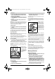
Lock the grinder spindle with
the spindle lock button 1. To
tighten the quick-clamping
nut, firmly turn the grinding
disc in clockwise direction.
A properly attached, undam-
aged quick-clamping nut can
be loosened by hand when
turning the knurled ring in an-
ticlockwise direction.
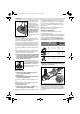
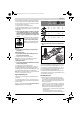
Never loosen a tight quick-
clamping nut with pliers. Al-
ways use the two-pin span-
ner. Insert the two-pin span-
ner as shown in the
illustration.
Grinding/Cutting Disc
Pay attention to the dimensions of the grinding tools. The
mounting hole diameter must fit the mounting flange without
play. Do not use reducers or adapters.
25
OBJ_BUCH-769-010.book Page 20 Friday, September 30, 2016 11:20 AM