
Installation Guide

FPP-RNAC-8A-4C | Operation and Installation Guide | 4.0 DIP Switch and Option Bus Settings
.
Bosch Security Systems, Inc. | 8/09 | F01U025431-02 19
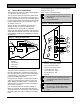
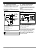
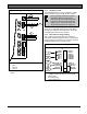
4.3 Conventional (Polarity Reversal) Inputs 1 and 2
Two factors determine how the four NAC outputs respond to input:
• Output protocol set on Switch S1 (refer to
Table 7 on page 17)
• Setting of Position 0 of Switch S2 (refer to
Table 8 on page 18
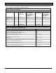
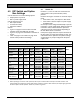
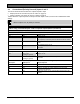
Table 9 shows the output responses to the input on NAC inputs 1 and 2, based on the combined DIP switch
settings.
When an input is OFF, its polarity is reversed.
Table 9: Using Conventional Inputs 1 and 2 to Operate Outputs (Switch 2, Position 0)
When Switch S2, Position 0 = OFF and Protocol is Pulsed, March Time, or Temporal:
NAC Input 1 NAC Input 2 Output Response
OFF OFF Outputs are off.
OFF ON NAC outputs 1 and 2 are off.
NAC outputs 3, 4 follow the protocol selected on the DIP switch.
ON OFF NAC outputs 1 and 2 follow the protocol selected on the DIP
switch.
NAC outputs 3 and 4 are off.
ON ON NAC outputs 1, 2, 3, and 4 follow the protocol selected on the
DIP switch.
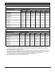
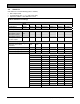
When Switch S2 Position 0 = ON and Protocol is Pulsed, March Time, Temporal:
NAC Input 1 NAC Input 2 Output Response
OFF OFF or ON
(Setting is ignored.)
Outputs are off.
ON OFF or ON
(Setting is ignored.)
NAC outputs 1, 2, 3, and 4 follow the protocol selected on the
DIP switch.
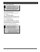
When Protocol is Wheelock, Gentex, System Sensor (Switch S2, Position 0 is ignored)
NAC Input 1 NAC Input 2 Output Response
OFF OFF Outputs are off.
OFF ON Not possible
ON OFF Strobe on, sounder off. Outputs follow the selected SYNC
protocol but are silenced.
ON ON Strobe and sounder are on. Outputs follow the selected SYNC
protocol.