
Installation Guide

FPP-RNAC-8A-4C | Operation and Installation Guide |
16 Bosch Security Systems, Inc. | 8/09 | F01U025431-02
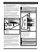
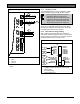
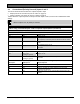
Figure 11: Wiring the NAC outputs and EOL
O
U
T
P
U
T
4
O
U
T
P
U
T
3
O
U
T
P
U
T
2
O
U
T
P
U
T
1
A+
B+
B-
B+
A+
B+
B-
B+
A+
B+
B-
B+
A+
B+
B-
B+
N
NNN
N
N
EOL
REF
1
2
3
4
1 1 K to 20 K
2 EOL*
3 Class B
4 Class A
* EOL supplied by control panel manufacturer (Bosch P/N:
25899)
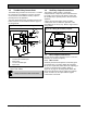
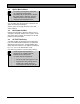
3.7.2 Auxiliary Circuits
The FPP-RNAC-8A-4C can be configured to supply
constant auxiliary power through its NAC outputs.
Reverse polarity connections of some
notification appliances might not be
detected by the FPP-RNAC-8A-4C NAC
supervision. Ensure that the notification
appliances are connected properly and
tested before installation is completed.
Use DIP Switch S1 positions 3, 4, 5, and 6 (refer to
Figure 12) to make the output always active. When
the output is configured as always active, the output
is unsupervised and no EOL is needed.
3.7.3 EOL Reference Programming
Add a resistor that matches the value of the EOL
used in the notification appliance circuit. This must be
in the range of 1 kΩ to 20 kΩ. If no resistor is present,
the RNAC defaults to the value of 2.2 kΩ.
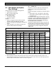
Figure 12: Auxiliary Power Configuration
SYNC 2
SYNC 1
SYNC 0
POWER 4
POWER 3
POWER 2
POWER 1
CNTRL 2
AC DELAY 1
AC DELAY 0
OPTION
ADDRESS
SYNC 2
SYNC 1
SYNC 0
NAC 4
NAC 3
NAC 2
NAC 1
CNTRL AL L
AC DELAY 1
AC DELAY 0
4
3
2
1
OPTION
ADDRESS
OFF ON
S1
S2
1
2
3
4
5
0
1
2
3
4
5
6
0
1
2
3
4
5
6
1 Configure SYNC pattern
2 Configure outputs for NAC or power supply
3 Input control
4 AC delay setting
5 Option address bus