
Installation Guide

FPP-RNAC-8A-4C | Operation and Installation Guide |
.
Bosch Security Systems, Inc. | 8/09 | F01U025431-02 15
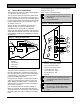
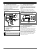
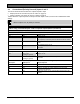
3.5 Trouble Relay Connections
The trouble relay provides one set of Form C contacts
for connection of an appliance of choice. The relay
can be wired in series with the auxiliary output to
provide power to the appliance.
The relay deactivates by the controlling section of the
board to indicate a fault condition. Refer to
Figure 9
for wiring details.
Figure 9: Wiring the Trouble Relay
T
R
O
U
B
L
E
AC
BOSCH 4998149856
T
R
O
U
B
L
E
I
N
P
U
T
2
NC
COM
NO
NC
COM
NO
1
2
3
4
5
1
1 EOL*
2 To FACP AC trouble input
3 Supervised
4 To FACP trouble input
5 Supervised
* EOL supplied by control panel manufacturer
(Bosch P/N: 25899)
Relays are shown in their normal state.
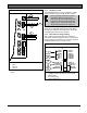
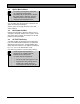
3.6 Auxiliary Output Connections
The auxiliary output provides a continuous,
unsupervised 24 V output to power external devices.
It is rated at 0.75 A and can be wired in series with
the trouble relay to provide power to the associated
appliance.
A short circuit on this output causes a trouble
condition but does not affect the operation of the
FPP-RNAC-8A-4C in any way. Refer to
Figure 10 for
wiring details.
Figure 10: Wiring the Auxiliary Outputs
O
U
T
P
U
T
1
- AUX POWER +
1
1 To accessory or device
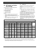
3.7 NAC Output Connections
Each of the four outputs provides up to 2.5 A at 24 V,
limited by an overall 8 A capacity.
3.7.1 NAC Circuits
Overload protection interrupts the circuit when given
an overload of 3 A or greater. When de-energized,
the circuit is supervised, which allows the reporting of
an open or shorted output condition. Refer to
Figure 11 on page 16 for wiring details. When the
total current draw from all four outputs and auxiliary
power exceeds 8 A, the output with the highest
current draw is turned off.