
Installation Guide

FPP-RNAC-8A-4C | Operation and Installation Guide |
14 Bosch Security Systems, Inc. | 8/09 | F01U025431-02
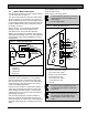
3.3 Option Bus Connections
The option bus (if used) runs to the terminals labeled
Y, G, B, and R (refer to
Figure 7).
You can use the option bus connection with a Bosch
Security Systems, Inc. FPA-1000 or FPD-7024 Fire
Alarm Control/Communicator. The FPP-RNAC-8A-4C
is a new option module type that can indicate specific
trouble conditions back to the control panel, such as
AC, battery, and so on.
Refer to Section
4.0 DIP Switch and Option Bus
Settings
on page 17 to set the address on the
FPP-RNAC-8A-4C for use with the option bus.
Refer to the FPA-1000-UL Installation and Operation
Guide (P/N F01U075420) or the FPD-7024 Operation
and Installation Guide (P/N F01U008458) for wiring
requirements.
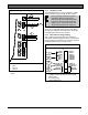
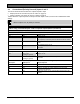
Figure 7: Wiring the Option Bus
OPTION BUS
R Y G B
GROUND FAULT
OPEN = DISABLE
CLOSE = ENABLE
1
2
3
4
5
1 Option Bus
2 Red wire
3 Yellow wire
4 Green wire
5 Black wire
3.4 NAC Input Connections
Two inputs can be used with 12 V or 24 V polarity
reversal outputs from a conventional control panel
that conform to NFPA 72, Class A or B (used instead
of the option bus connection). Refer to the control
panel’s compatibility information.
Polarity reversal on Input 1 activates NAC Outputs 1
and 2; Input 2 activates NAC Outputs 3 and 4. DIP
switch settings allow NAC Input 1 to control all four
outputs (refer to Section
4.0 DIP Switch and Option
Bus Settings
on page 17).
If the control panel detects a trouble condition on
either set of outputs, the appropriate EOL device is
disconnected from the reversal loop. These inputs are
electrically isolated from the controlling section of the
board.
The FPP-RNAC-8A-4C can be placed anywhere on
an FACP’s NAC circuit.
Refer to
Figure 8 for wiring details.
Connect either the option bus or the NAC
Input terminals on the FPP RNAC 8A-4C
to the FACP.
Do not connect both.
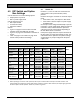
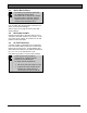
Figure 8: Wiring the NAC Inputs
T
R
O
U
B
L
E
I
N
P
U
T
1
I
N
P
U
T
2
EOL
REF
OUT_2 +
IN_2 +
IN_2 -
OUT_2 -
OUT_1 +
IN_1 +
IN_1 -
OUT_1 -
N
N
1
2
3
4
5
6
7
8
1 Class A
2 Return to FACP NAC output
3 From FACP NAC output
4 Return to FACP NAC output
5 To next device or EOL
6 From FACP NAC output
7 To next device or EOL
8 Class B
The EOL resistor value depends on the
conventional panel. Select a value from
1 k to 20 k.
When connecting to the FPD-7024 using
the option bus, all FPP-RNAC-8A-4C
power supplies must be on the same
zone.