
Installation Manual
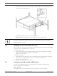
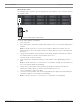
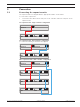
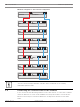
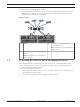
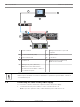
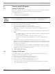
Table Of Contents
- Table of contents
- 1 Safety
- 2 Before you begin
- 3 System overview
- 4 Installation
- 5 Connection
- 6 Turning on/off AC power
- 7 Configuring the storage system
- 8 Maintenance
- Blank Page
- Blank Page
- Blank Page

DSA E-Series (E2800 12-bay) Connection | en 25
Bosch Sicherheitssysteme GmbH Installaton manual 2018.02 | V1 | DOC
To connect the controller unit to the network:
4 Connect the cable from the iSCSI host port of the controller unit to a port on the switch.
Note: Make sure that the iSCSI ports of the controller unit and the relevant IP camera
ports are in the same range on the switch.
Switch topology
2 3
1
Switch
1 Switch 2 Controller A - iSCSI host interface
ports (RJ45 Base‑T)
Note: Optionally, use the optical host
interface ports.
3 Controller B - iSCSI host ports (RJ45
Base‑T)
Note: Optionally, use the optical host
interface ports.
5.3 Connecting the controller unit to the management hosts
The management host directly manages storage arrays over an out-of-band network. This
section describes how to set up an out-of-band connection between the Ethernet port of a
controller unit and the management host.
To set up an out-of-band connection:
1. Connect Ethernet cables between port 1 of controller A and port 1 of controller B to an
external Ethernet switch or hub.
2. Connect the management host to the Ethernet switch or hub.