
Installation Manual
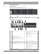
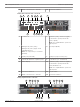
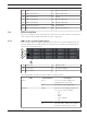
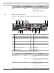
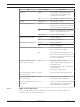
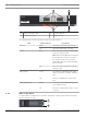
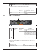
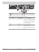
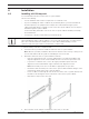

Table Of Contents
- Table of contents
- 1 Safety
- 2 Before you begin
- 3 System overview
- 4 Installation
- 5 Connection
- 6 Turning on/off AC power
- 7 Configuring the storage system
- 8 Maintenance
- Blank Page
- Blank Page
- Blank Page

DSA E-Series (E2800 12-bay) System overview | en 13
Bosch Sicherheitssysteme GmbH Installaton manual 2018.02 | V1 | DOC
1 IOMA 2 IOMA - SAS port1
3 IOMA - SAS port2 4 IOMA - SAS port3
5 IOMA - SAS port4 6 IOMB
7 IOMB - SAS port1 8 IOMB - SAS port2
9 IOMB - SAS port3 10 IOMB - SAS port4
11 Power-fan canister1 12 On/off switch
13 Mains connection 100 - 240 VAC 14 Power-fan canister2
3.2 LED description
There are several LEDs on the front and rear of the chassis. The LEDs show the over-all status
of the system and the activity and health of specific components.
3.2.1 LEDs on the operator display panel
Each controller unit and expansion unit has LEDs located on the operator display panel. The
operator display panel is visible through the front bezel of a controller unit and through the
left end cap of an expansion unit.
1
5
2
3
4
1 Power LED 2 Attention LED
3 Locate LED 4 7-segment display
5 Drive canister
The following table describes the LEDs and their operational states:
LED Status indicator Description
Power Green One or more power supplies are
supplying power to the unit.
Off The unit is not receiving power.
Attention Amber There is an error with the function of
one or more of the following:
– Unit
– Drives
– IOMs
– Power supplies
– Fans
Off The unit, drives, IOMs, power supply,
and fans are functioning correctly.