
Installation Manual
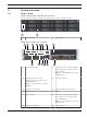
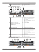
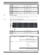
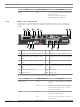
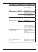
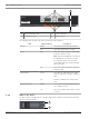
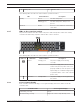
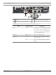
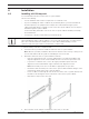

Table Of Contents
- Table of contents
- 1 Safety
- 2 Before you begin
- 3 System overview
- 4 Installation
- 5 Connection
- 6 Turning on/off AC power
- 7 Configuring the storage system
- 8 Maintenance
- Blank Page
- Blank Page
- Blank Page

12 en | System overview DSA E-Series (E2800 12-bay)
2018.02 | V1 | DOC Installaton manual Bosch Sicherheitssysteme GmbH
13 Mains connection 100 - 240 VAC 14 Power-fan canister2
12-bay dual controller unit - rear view
1 5
9
2
6
3
7
4
8
1410 11 12 13
1 ControllerA 2 Channel3 (left) / Channel4 (right) -
Host interface ports (Dual 10GB
iSCSI, optical)
Note: Use only RJ45 Base‑T ports or
optical ports.
3 Management port1 (left) /
Management port2 (right) - Dual
1Gigabit Ethernet
Note: Use only Port1 per controller
(default).
4 Serial port (RJ45)
5 Serial port (mini USB) 6 USB port (only for factory use)
7 Dual 12Gb SAS drive expansion ports 8 ControllerB (see ControllerA)
9 Status display 10 Channel5 (left) / Channel6 (right) -
Host interface ports (Dual 10GB
iSCSI, RJ45 Base‑T)
Note: Use only RJ45 Base‑T ports or
optical ports.
11 Power-fan canister1 12 On/off switch
13 Mains connection 100 - 240 VAC 14 Power-fan canister2
12-bay expansion unit - rear view
9 10
11 12 13 14
1 52
6
3
7
4 8