
Installation Manual
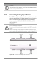
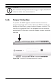
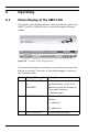
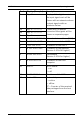
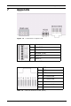
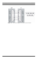
Table Of Contents
- 1 Important Information
- 2 Safety Instructions
- 3 Introduction
- 4 Technical Data
- 5 Installing
- 5.1 Mounting
- 5.2 Unmounting
- 5.3 Opening the Case
- 5.4 Closing the Case
- 5.5 Cabling
- 5.6 Grounding and Shielding
- 5.7 Connecting Power Supply
- 5.8 Ethernet Interface
- 5.9 RS-485 Host Interface
- 5.10 RS-232 Host Interface
- 5.11 DIL switch selector
- 5.12 RS-485 for extension modules
- 5.13 Wiegand Interface for Card Readers
- 5.14 Connecting Relay Outputs
- 5.15 Connecting Analog Input Devices
- 5.16 Tamper Protection
- 6 Operating
- 7 Appendix

AMC2 4W Appendix | en 59
Bosch Sicherheitssysteme GmbH Installation manual | V 7.6 | 2008.12
7 Appendix
Figure 7.1 Connectors on upper PCB
Table 7.1 RS-485 host on upper PCB
Table 7.2 Ethernet Network socket (RJ45)
1Shield
2 Data RxTx+
3 Data RxTx-
4Ground (PAG)
5 Data Tx+
6 Data Tx-
1TXD+
2TXD-
3RXD+
4not connected
5not connected
6RXD-
7not connected
8not connected