
Installation Manual
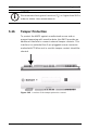
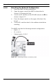
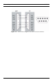
Table Of Contents
- 1 Important Information
- 2 Safety Instructions
- 3 Introduction
- 4 Technical Data
- 5 Installing
- 5.1 Mounting
- 5.2 Unmounting
- 5.3 Opening the Case
- 5.4 Closing the Case
- 5.5 Cabling
- 5.6 Grounding and Shielding
- 5.7 Connecting Power Supply
- 5.8 Ethernet Interface
- 5.9 RS-485 Host Interface
- 5.10 RS-232 Host Interface
- 5.11 DIL switch selector
- 5.12 RS-485 for extension modules
- 5.13 Wiegand Interface for Card Readers
- 5.14 Connecting Relay Outputs
- 5.15 Connecting Analog Input Devices
- 5.16 Tamper Protection
- 6 Operating
- 7 Appendix

58 en | Operating AMC2 4W
| V 7.6 | 2008.12 Installation manual Bosch Sicherheitssysteme GmbH
6.3.2 Resetting the Network Configuration
1. Reset the AMC2 as described above.
2. Open the upper case of the AMC2 as described in
Section 5.3 Opening the Case.
3. Set all six DIL switches of the RS-485 selector to ON as
shown in Figure 6.3.
4. Press the tamper switch on the upper left side of the
board.
5. Set the DIL switches back in the address state before
resetting.
The AMC2 now has the following network configuration:
–DHCP = 1
– IP = 0.0.0.0
– Subnet mask = 0.0.0.0
Figure 6.3 Resetting the AMC2 to delivery state