
Installation Manual
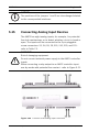
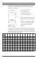
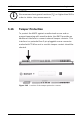
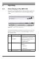
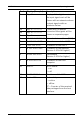
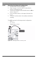
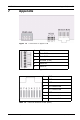
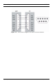
Table Of Contents
- 1 Important Information
- 2 Safety Instructions
- 3 Introduction
- 4 Technical Data
- 5 Installing
- 5.1 Mounting
- 5.2 Unmounting
- 5.3 Opening the Case
- 5.4 Closing the Case
- 5.5 Cabling
- 5.6 Grounding and Shielding
- 5.7 Connecting Power Supply
- 5.8 Ethernet Interface
- 5.9 RS-485 Host Interface
- 5.10 RS-232 Host Interface
- 5.11 DIL switch selector
- 5.12 RS-485 for extension modules
- 5.13 Wiegand Interface for Card Readers
- 5.14 Connecting Relay Outputs
- 5.15 Connecting Analog Input Devices
- 5.16 Tamper Protection
- 6 Operating
- 7 Appendix

54 en | Operating AMC2 4W
| V 7.6 | 2008.12 Installation manual Bosch Sicherheitssysteme GmbH
6 Operating
6.1 Status Display of the AMC2 4W
The liquid crystal display delivers status information about the
AMC2. Push the 'Dialog' button to switch between different
modes.
Figure 6.1 Location of the ’Dialog’ button
The selected display mode remains set until the next time the
button is pressed. The order of the display pages is shown in
the following table.
Push Display (Example) Description
0 V01.00 02.03.07
or
WIEGAND
Software versions and date of
the downloader - every 5 sec.
alternating with the display of
the reader interface.
(= default page)
1 99999876543210 A BOSCH serial number and bus
address:
A = address 1
...
H = address 8
2 02.06 15:35:15 Current date and time