
Installation Manual
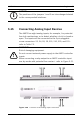
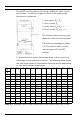
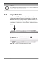
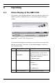
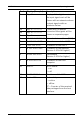
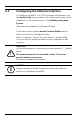
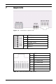
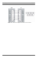
Table Of Contents
- 1 Important Information
- 2 Safety Instructions
- 3 Introduction
- 4 Technical Data
- 5 Installing
- 5.1 Mounting
- 5.2 Unmounting
- 5.3 Opening the Case
- 5.4 Closing the Case
- 5.5 Cabling
- 5.6 Grounding and Shielding
- 5.7 Connecting Power Supply
- 5.8 Ethernet Interface
- 5.9 RS-485 Host Interface
- 5.10 RS-232 Host Interface
- 5.11 DIL switch selector
- 5.12 RS-485 for extension modules
- 5.13 Wiegand Interface for Card Readers
- 5.14 Connecting Relay Outputs
- 5.15 Connecting Analog Input Devices
- 5.16 Tamper Protection
- 6 Operating
- 7 Appendix

AMC2 4W Installing | en 53
Bosch Sicherheitssysteme GmbH Installation manual | V 7.6 | 2008.12
5.16 Tamper Protection
To protect the AMC2 against unauthorized access and so
prevent tampering with sensitive data, the AMC2 provides an
additional interface to connect external tamper contacts. This
interface is a potential-free 2-pin pluggable screw connector
marked with T. When not in use this tamper contact should be
shorted.
Figure 5.25 Location of the tamper protection contact
i
NOTICE!
We recommend using serial resistors (R
S
) no higher than 5K6 in
order to obtain clear measurements.