
Installation Manual
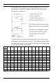
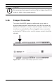
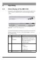
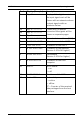
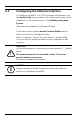
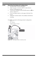
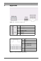
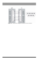
Table Of Contents
- 1 Important Information
- 2 Safety Instructions
- 3 Introduction
- 4 Technical Data
- 5 Installing
- 5.1 Mounting
- 5.2 Unmounting
- 5.3 Opening the Case
- 5.4 Closing the Case
- 5.5 Cabling
- 5.6 Grounding and Shielding
- 5.7 Connecting Power Supply
- 5.8 Ethernet Interface
- 5.9 RS-485 Host Interface
- 5.10 RS-232 Host Interface
- 5.11 DIL switch selector
- 5.12 RS-485 for extension modules
- 5.13 Wiegand Interface for Card Readers
- 5.14 Connecting Relay Outputs
- 5.15 Connecting Analog Input Devices
- 5.16 Tamper Protection
- 6 Operating
- 7 Appendix

AMC2 4W Installing | en 51
Bosch Sicherheitssysteme GmbH Installation manual | V 7.6 | 2008.12
5.15 Connecting Analog Input Devices
The AMC2 has eight analog inputs, for example, for potential-
free lock mechanisms, or to detect whether a lock is closed or
open. The inputs will be connected to the 2-pin pluggable
screw connectors: S3, S4, S8, S9, S15, S16, S20, and S21 -
refer to Table 7.5.
Figure 5.24 Location of the analog input connectors
i
NOTICE!
The positions of the jumpers 1 and 2 are interchanged related
to the corresponded interfaces.
!
WARNING!
Risk of damaging equipment.
Do not connect external power supply to the AMC2 controller
inputs.
When connecting a relay output to an AMC2 controller input
use dry mode with potential-free contact - refer to Figure 5.21.