
Installation Manual
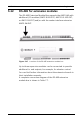
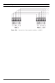
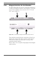
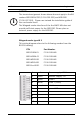
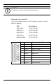
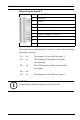
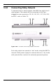
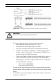
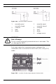
Table Of Contents
- 1 Important Information
- 2 Safety Instructions
- 3 Introduction
- 4 Technical Data
- 5 Installing
- 5.1 Mounting
- 5.2 Unmounting
- 5.3 Opening the Case
- 5.4 Closing the Case
- 5.5 Cabling
- 5.6 Grounding and Shielding
- 5.7 Connecting Power Supply
- 5.8 Ethernet Interface
- 5.9 RS-485 Host Interface
- 5.10 RS-232 Host Interface
- 5.11 DIL switch selector
- 5.12 RS-485 for extension modules
- 5.13 Wiegand Interface for Card Readers
- 5.14 Connecting Relay Outputs
- 5.15 Connecting Analog Input Devices
- 5.16 Tamper Protection
- 6 Operating
- 7 Appendix

50 en | Installing AMC2 4W
| V 7.6 | 2008.12 Installation manual Bosch Sicherheitssysteme GmbH
Figure 5.22 Recovery diode schematic
Each relay output has a separate jumper setting on the
underside of the circuit board to select wet (D 2) or dry (D 1)
mode.
Figure 5.23 Location of relay output jumpers (bottom side)
1 normally open/
normally closed
1 normally open/
normally closed
2 common 2 common
3load 3load
4 diode 4 diode
5 voltage source
!
WARNING!
Risk of Damage!
Do not connect externally powered devices in wet mode. This
can damage the AMC2.