
Installation Manual
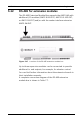
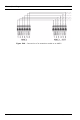
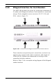
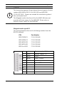
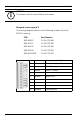
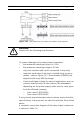
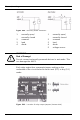
Table Of Contents
- 1 Important Information
- 2 Safety Instructions
- 3 Introduction
- 4 Technical Data
- 5 Installing
- 5.1 Mounting
- 5.2 Unmounting
- 5.3 Opening the Case
- 5.4 Closing the Case
- 5.5 Cabling
- 5.6 Grounding and Shielding
- 5.7 Connecting Power Supply
- 5.8 Ethernet Interface
- 5.9 RS-485 Host Interface
- 5.10 RS-232 Host Interface
- 5.11 DIL switch selector
- 5.12 RS-485 for extension modules
- 5.13 Wiegand Interface for Card Readers
- 5.14 Connecting Relay Outputs
- 5.15 Connecting Analog Input Devices
- 5.16 Tamper Protection
- 6 Operating
- 7 Appendix

AMC2 4W Installing | en 49
Bosch Sicherheitssysteme GmbH Installation manual | V 7.6 | 2008.12
Figure 5.21 Wet mode and dry mode of the AMC2 relay outputs
To prevent damage to the relays please remember:
– the maximum switching current is 1.25 A
– the maximum switching voltage is 30 Vdc
– only ohm resistive load can be connected to the relay
– inductive loads have to be short circuited using recovery
diodes - refer to Figure 5.22. These diodes (1N4004) are
supplied with every AMC2 package.
– If you need higher voltage for special applications you can
connect external relays to the outputs. Recommended,
depending on the power supply mode, are the relay types
from the Wieland company:
– Flare move 12DC1W10A
– Flare move 24DC1W16A
If using locally manufactured products, please ensure that the
specifications of the product are identical with the those listed
above.
A complete connection diagram of the relay output connectors
is shown in Table 7.6.
!
WARNING!
Please note the following specifications.