
Installation Manual
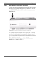
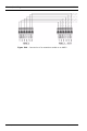
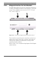
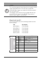
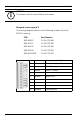
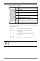
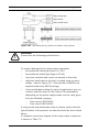
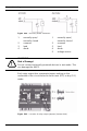
Table Of Contents
- 1 Important Information
- 2 Safety Instructions
- 3 Introduction
- 4 Technical Data
- 5 Installing
- 5.1 Mounting
- 5.2 Unmounting
- 5.3 Opening the Case
- 5.4 Closing the Case
- 5.5 Cabling
- 5.6 Grounding and Shielding
- 5.7 Connecting Power Supply
- 5.8 Ethernet Interface
- 5.9 RS-485 Host Interface
- 5.10 RS-232 Host Interface
- 5.11 DIL switch selector
- 5.12 RS-485 for extension modules
- 5.13 Wiegand Interface for Card Readers
- 5.14 Connecting Relay Outputs
- 5.15 Connecting Analog Input Devices
- 5.16 Tamper Protection
- 6 Operating
- 7 Appendix

48 en | Installing AMC2 4W
| V 7.6 | 2008.12 Installation manual Bosch Sicherheitssysteme GmbH
5.14 Connecting Relay Outputs
To operate locks or alarm systems, the AMC2 has eight form C
relay outputs. The outputs will be connected to the 3-pin
pluggable screw connectors: S5, S6, S10, S11, S17, S18, S22,
and S23 - refer to Table 7.6.
Figure 5.20 Location of the relay output connectors
Each relay output can operate in ‘wet’ mode, using the AMC2's
internal 12Vdc power supply for external devices or ‘dry’ mode
with potential free contacts for externally powered systems.