
Installation Manual
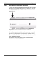
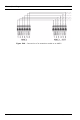
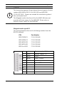
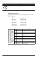
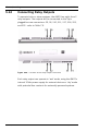
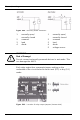
Table Of Contents
- 1 Important Information
- 2 Safety Instructions
- 3 Introduction
- 4 Technical Data
- 5 Installing
- 5.1 Mounting
- 5.2 Unmounting
- 5.3 Opening the Case
- 5.4 Closing the Case
- 5.5 Cabling
- 5.6 Grounding and Shielding
- 5.7 Connecting Power Supply
- 5.8 Ethernet Interface
- 5.9 RS-485 Host Interface
- 5.10 RS-232 Host Interface
- 5.11 DIL switch selector
- 5.12 RS-485 for extension modules
- 5.13 Wiegand Interface for Card Readers
- 5.14 Connecting Relay Outputs
- 5.15 Connecting Analog Input Devices
- 5.16 Tamper Protection
- 6 Operating
- 7 Appendix

46 en | Installing AMC2 4W
| V 7.6 | 2008.12 Installation manual Bosch Sicherheitssysteme GmbH
Wiegand reader type W 3
This wiring diagram refers to the following readers from the
BOSCH catalog:
i
NOTICE!
The beeper will be controlled by the reader.
CTN Part Number
ARD-AYK12 F.01U.075.408
ARD-AYJ12 F.01U.075.388
ARD-AYH12 F.01U.075.389
ARD-AYQ12 F.01U.075.390
ARD-AYCE65B F.01U.075.391
1 red Power supply - 12 V+
2 black Reader Supply - 0V
3 green Data 0
4 white Data 1 (clock)
5-
6brown green LED
7-
8-
9-
10 purple Card present