
Installation Manual
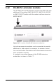
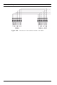
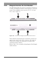
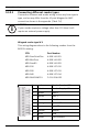
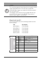
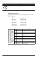
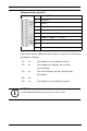
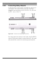
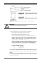
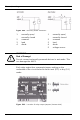
Table Of Contents
- 1 Important Information
- 2 Safety Instructions
- 3 Introduction
- 4 Technical Data
- 5 Installing
- 5.1 Mounting
- 5.2 Unmounting
- 5.3 Opening the Case
- 5.4 Closing the Case
- 5.5 Cabling
- 5.6 Grounding and Shielding
- 5.7 Connecting Power Supply
- 5.8 Ethernet Interface
- 5.9 RS-485 Host Interface
- 5.10 RS-232 Host Interface
- 5.11 DIL switch selector
- 5.12 RS-485 for extension modules
- 5.13 Wiegand Interface for Card Readers
- 5.14 Connecting Relay Outputs
- 5.15 Connecting Analog Input Devices
- 5.16 Tamper Protection
- 6 Operating
- 7 Appendix

44 en | Installing AMC2 4W
| V 7.6 | 2008.12 Installation manual Bosch Sicherheitssysteme GmbH
5.13.1 Connecting different reader types
Connection schemes and reader wiring colors vary from type to
type, and so may differ from the 10-pole Wiegand to AMC
connection shown in the appendix (Table 7.4)
Wiegand reader type W 1
This wiring diagram refers to the following readers from the
BOSCH catalog:
i
NOTICE!
If your reader requires a voltage other than 12V then it will
require an external power supply.
CTN Part Number
ARD-ProxPointPlus 4.998.141.821
ARD-MiniProx 4.998.141.822
ARD-Prox80 4.998.141.823
ARD-R10 4.998.127.612
ARD-R30 4.998.127.613
ARD-R40 4.998.127.614
ARD-RK40-AMC01 F.01U.514.655
1 red Reader Supply - 12V+
2 black Reader Supply - 0V
3 green Data 0
4 white Data 1
5drain Shield
6 orange green LED
7 brown red LED
8 yellow Beeper
9blue Hold
10 violet Card Present