
Installation Manual
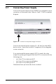
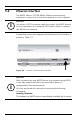
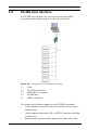
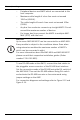
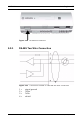
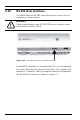
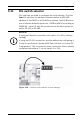
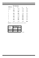
Table Of Contents
- 1 Important Information
- 2 Safety Instructions
- 3 Introduction
- 4 Technical Data
- 5 Installing
- 5.1 Mounting
- 5.2 Unmounting
- 5.3 Opening the Case
- 5.4 Closing the Case
- 5.5 Cabling
- 5.6 Grounding and Shielding
- 5.7 Connecting Power Supply
- 5.8 Ethernet Interface
- 5.9 RS-485 Host Interface
- 5.10 RS-232 Host Interface
- 5.11 DIL switch selector
- 5.12 RS-485 for extension modules
- 5.13 Wiegand Interface for Card Readers
- 5.14 Connecting Relay Outputs
- 5.15 Connecting Analog Input Devices
- 5.16 Tamper Protection
- 6 Operating
- 7 Appendix

AMC2 4W Installing | en 39
Bosch Sicherheitssysteme GmbH Installation manual | V 7.6 | 2008.12
5.11 DIL switch selector
DIL switches are used to configure the host settings. The first
four DIL switches for address selection define the RS-485
address of the AMC2 in a RS-485 bus system. Switch 5 selects
one of the two different protocols, SDEB and BPA (according to
DIN6619). Switch 6 sets the connection to the host system to
either RS-232 or RS-485.
Figure 5.16 Location of the selector for host settings
i
NOTICE!
If using an Ethernet connection, set switch 1 to ON (= factory
setting).
If using an RS-232 connection, set the address by configuring it
in the Access Control System (ACE Device Editor or Access PE
Configurator). This is a point-to-point connection that is usually
configured as address 1, so set switch 1 to ON.