
Installation Manual
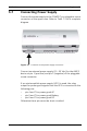
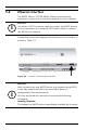
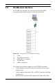
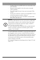
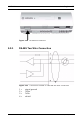
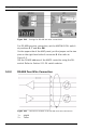
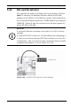
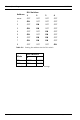
Table Of Contents
- 1 Important Information
- 2 Safety Instructions
- 3 Introduction
- 4 Technical Data
- 5 Installing
- 5.1 Mounting
- 5.2 Unmounting
- 5.3 Opening the Case
- 5.4 Closing the Case
- 5.5 Cabling
- 5.6 Grounding and Shielding
- 5.7 Connecting Power Supply
- 5.8 Ethernet Interface
- 5.9 RS-485 Host Interface
- 5.10 RS-232 Host Interface
- 5.11 DIL switch selector
- 5.12 RS-485 for extension modules
- 5.13 Wiegand Interface for Card Readers
- 5.14 Connecting Relay Outputs
- 5.15 Connecting Analog Input Devices
- 5.16 Tamper Protection
- 6 Operating
- 7 Appendix

AMC2 4W Installing | en 37
Bosch Sicherheitssysteme GmbH Installation manual | V 7.6 | 2008.12
Figure 5.14 Settings for RS-485 four wire connection
For RS-485 four wire connection, set the AMC-MUX DIL switch
at positions 3, 5 and 6 to ON. On the upper side of the AMC
panel, put the jumper on the two pins on the right hand side of
the connector 8. Also refer to Figure 3.3. Set the RS-485
address of the AMC2 controller using the DIL switch. Refer to
Section 5.11 DIL switch selector. A complete connection
diagram of the RS-485 host interface is shown in Table 7.1.
3 = TxRx-
4 = signal ground
5 = Tx+
6 = Tx-