
Installation Manual
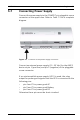
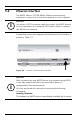
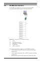
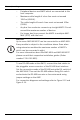
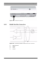
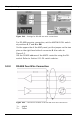
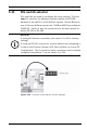
Table Of Contents
- 1 Important Information
- 2 Safety Instructions
- 3 Introduction
- 4 Technical Data
- 5 Installing
- 5.1 Mounting
- 5.2 Unmounting
- 5.3 Opening the Case
- 5.4 Closing the Case
- 5.5 Cabling
- 5.6 Grounding and Shielding
- 5.7 Connecting Power Supply
- 5.8 Ethernet Interface
- 5.9 RS-485 Host Interface
- 5.10 RS-232 Host Interface
- 5.11 DIL switch selector
- 5.12 RS-485 for extension modules
- 5.13 Wiegand Interface for Card Readers
- 5.14 Connecting Relay Outputs
- 5.15 Connecting Analog Input Devices
- 5.16 Tamper Protection
- 6 Operating
- 7 Appendix

36 en | Installing AMC2 4W
| V 7.6 | 2008.12 Installation manual Bosch Sicherheitssysteme GmbH
Figure 5.12 Settings for RS-485 two wire connections
For RS-485 two wire connection, set the AMC-MUX DIL switch
at positions 3, 7 and 8 to ON.
On the upper side of the AMC panel, put the jumper on the two
pins on the right hand side of connector 8. Also refer to
Figure 3.3.
Set the RS-485 address of the AMC2 controller using the DIL
switch. Refer to Section 5.11 DIL switch selector.
5.9.2 RS-485 Four Wire Connection
Figure 5.13 Connection scheme of an RS-485 four wire connection
1 = shield
2 = TxRx+