
Installation Manual
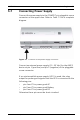
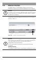
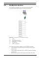
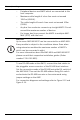
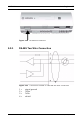
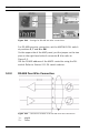
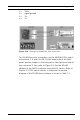
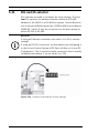
Table Of Contents
- 1 Important Information
- 2 Safety Instructions
- 3 Introduction
- 4 Technical Data
- 5 Installing
- 5.1 Mounting
- 5.2 Unmounting
- 5.3 Opening the Case
- 5.4 Closing the Case
- 5.5 Cabling
- 5.6 Grounding and Shielding
- 5.7 Connecting Power Supply
- 5.8 Ethernet Interface
- 5.9 RS-485 Host Interface
- 5.10 RS-232 Host Interface
- 5.11 DIL switch selector
- 5.12 RS-485 for extension modules
- 5.13 Wiegand Interface for Card Readers
- 5.14 Connecting Relay Outputs
- 5.15 Connecting Analog Input Devices
- 5.16 Tamper Protection
- 6 Operating
- 7 Appendix

34 en | Installing AMC2 4W
| V 7.6 | 2008.12 Installation manual Bosch Sicherheitssysteme GmbH
– Peripheral devices are AMC2 which are connected to the
host computer.
– Maximum cable length of a bus line must not exceed
1200 m (4000ft).
– The cable length of branch lines must not exceed 100m
(330ft).
– Any bus line conductor connects up to eight AMC2. Do not
exceed the maximum number of devices.
– For longer bus lines connect the AMC2 to multiple AMC-
MUX (-EXT) with the host.
To use RS-485 mode at the AMC2, connect the data cables to
the pluggable screw connector of the RS-485 host interface.
Set the connection mode of the RS-485 using the DIL switch of
the AMC-MUX. Then set the RS-485 address using DIL switch
and activate the RS-485 two-wire or four-wire mode using
jumper settings on the AMC.
For connection diagrams and settings refer to Figure 5.12 and
Figure 5.14.
i
NOTICE!
Up to seven AMC-MUX-EXT can be connected to an AMC-MUX.
Every module is subject to the conditions above. Even when
using extension modules the maximum number of AMC2’s
which can be connected is eight.
For more information about the AMC-MUX and AMC-MUX-EXT
please consult their respective installation guides (Order
number F.01U.012.855).