
Installation Manual
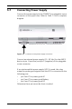
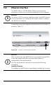
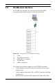
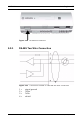
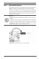
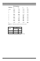
Table Of Contents
- 1 Important Information
- 2 Safety Instructions
- 3 Introduction
- 4 Technical Data
- 5 Installing
- 5.1 Mounting
- 5.2 Unmounting
- 5.3 Opening the Case
- 5.4 Closing the Case
- 5.5 Cabling
- 5.6 Grounding and Shielding
- 5.7 Connecting Power Supply
- 5.8 Ethernet Interface
- 5.9 RS-485 Host Interface
- 5.10 RS-232 Host Interface
- 5.11 DIL switch selector
- 5.12 RS-485 for extension modules
- 5.13 Wiegand Interface for Card Readers
- 5.14 Connecting Relay Outputs
- 5.15 Connecting Analog Input Devices
- 5.16 Tamper Protection
- 6 Operating
- 7 Appendix

32 en | Installing AMC2 4W
| V 7.6 | 2008.12 Installation manual Bosch Sicherheitssysteme GmbH
5.8 Ethernet Interface
The AMC2 offers a 10/100 Mbit/s Ethernet auto-sensing
interface to connect to a local area network or host computer.
A complete connection diagram of the Ethernet host interface is
shown in Table 7.2.
Figure 5.8 Location of the Ethernet interface
i
NOTICE!
Use either a CAT5 crossover cable to connect the AMC2 directly
to host computer, or a standard CAT5 patch cable to connect
the AMC2 via a network.
i
NOTICE!
After connecting a new AMC2 device to a network using DHCP,
it can take some time before the new AMC2 device is
recognized by the remote server.
You can accelerate this process by running the following
command:
ipconfig /flushdns
This makes the AMC2 device immediately available by its name.