
Installation Manual

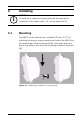
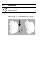
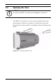
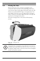
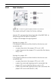
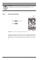
Table Of Contents
- 1 Important Information
- 2 Safety Instructions
- 3 Introduction
- 4 Technical Data
- 5 Installing
- 5.1 Mounting
- 5.2 Unmounting
- 5.3 Opening the Case
- 5.4 Closing the Case
- 5.5 Cabling
- 5.6 Grounding and Shielding
- 5.7 Connecting Power Supply
- 5.8 Ethernet Interface
- 5.9 RS-485 Host Interface
- 5.10 RS-232 Host Interface
- 5.11 DIL switch selector
- 5.12 RS-485 for extension modules
- 5.13 Wiegand Interface for Card Readers
- 5.14 Connecting Relay Outputs
- 5.15 Connecting Analog Input Devices
- 5.16 Tamper Protection
- 6 Operating
- 7 Appendix

AMC2 4W Installing | en 29
Bosch Sicherheitssysteme GmbH Installation manual | V 7.6 | 2008.12
5.6.1 Host Interface
Figure 5.5 Location of ground jumper RS-485 host interface
The jumper setting A1 shows the factory settings.
Jumper JP1 connects the internal ground of the AMC2 4W to
the ground of the RS-485 host interface.
Jumper JP2 manages the signal ground.
Settings for jumper JP1:
If the ground conductor and the shield on the host are not
connected and ...
– no party line exists, the jumper JP1 is set (= A2)
– a party line exists, the jumper JP1 is set at the first device,
only (= A2)
Settings for jumper JP2:
If the ground conductor and the shield on the host are not
connected and ...
– no party line exists, the jumper JP2 is set (= A3)
– a party line exists and signal ground is connected, the
jumper JP2 is set at the first device, only (= A3)
– a party line exists and signal ground is not connected, the
jumper JP2 is set at all devices (= A3)