
Installation Manual

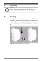
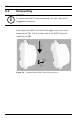
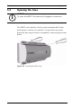
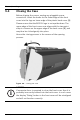
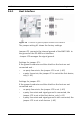
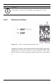
Table Of Contents
- 1 Important Information
- 2 Safety Instructions
- 3 Introduction
- 4 Technical Data
- 5 Installing
- 5.1 Mounting
- 5.2 Unmounting
- 5.3 Opening the Case
- 5.4 Closing the Case
- 5.5 Cabling
- 5.6 Grounding and Shielding
- 5.7 Connecting Power Supply
- 5.8 Ethernet Interface
- 5.9 RS-485 Host Interface
- 5.10 RS-232 Host Interface
- 5.11 DIL switch selector
- 5.12 RS-485 for extension modules
- 5.13 Wiegand Interface for Card Readers
- 5.14 Connecting Relay Outputs
- 5.15 Connecting Analog Input Devices
- 5.16 Tamper Protection
- 6 Operating
- 7 Appendix

28 en | Installing AMC2 4W
| V 7.6 | 2008.12 Installation manual Bosch Sicherheitssysteme GmbH
5.6 Grounding and Shielding
The main grounding point at the AMC2 is connected to pin 2 of
the power supply connector - see Table 7.3.
It is good practice to shield all wires carrying low level signals.
The AMC2 allows you to create a central ground or shielding
point, simply by setting certain jumpers. Set these jumpers only
if grounding or shielding is not achieved by other means.
i
NOTICE!
These specifications apply to power supply, readers, relay
outputs, and extension interface.
Regarding inputs, specific voltage-drop values need to be taken
into account. Refer to Table 5.3
i
NOTICE!
In general the following apply:
– If the devices have their own power supplies, the shielding
is applied to one side only.
The free end should be insulated to avoid inadvertent
connections.
– If one device is fed power by another, the cable shielding
should be applied to both sides.
!
WARNING!
Please ensure that no ground loops are formed.