
Installation Manual

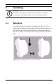
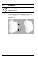
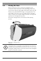
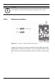
Table Of Contents
- 1 Important Information
- 2 Safety Instructions
- 3 Introduction
- 4 Technical Data
- 5 Installing
- 5.1 Mounting
- 5.2 Unmounting
- 5.3 Opening the Case
- 5.4 Closing the Case
- 5.5 Cabling
- 5.6 Grounding and Shielding
- 5.7 Connecting Power Supply
- 5.8 Ethernet Interface
- 5.9 RS-485 Host Interface
- 5.10 RS-232 Host Interface
- 5.11 DIL switch selector
- 5.12 RS-485 for extension modules
- 5.13 Wiegand Interface for Card Readers
- 5.14 Connecting Relay Outputs
- 5.15 Connecting Analog Input Devices
- 5.16 Tamper Protection
- 6 Operating
- 7 Appendix

26 en | Installing AMC2 4W
| V 7.6 | 2008.12 Installation manual Bosch Sicherheitssysteme GmbH
5.4 Closing the Case
Before aligning the covers, unplug any pluggable screw
connectors. Insert the hooks on the lower edge of the front
cover into the lugs on lower edge of the plastic back cover [1].
Please ensure that the BOSCH logo is not upside-down. The
upper edge of the front cover now aligns with the two-point
snap-in closures on the upper edge of the back cover [2], and
may thus be clicked gently into place.
Hence the closing process is the reverse of the opening
process.
Figure 5.4 Closing the case
i
NOTICE!
If excessive force is required to close the front cover then it is
probably incorrectly hooked into the back cover. In such cases
the display ’Dialog’ button in the front cover will be misaligned
and will not function correctly.