
Installation Manual

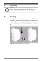
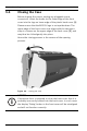
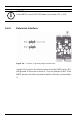
Table Of Contents
- 1 Important Information
- 2 Safety Instructions
- 3 Introduction
- 4 Technical Data
- 5 Installing
- 5.1 Mounting
- 5.2 Unmounting
- 5.3 Opening the Case
- 5.4 Closing the Case
- 5.5 Cabling
- 5.6 Grounding and Shielding
- 5.7 Connecting Power Supply
- 5.8 Ethernet Interface
- 5.9 RS-485 Host Interface
- 5.10 RS-232 Host Interface
- 5.11 DIL switch selector
- 5.12 RS-485 for extension modules
- 5.13 Wiegand Interface for Card Readers
- 5.14 Connecting Relay Outputs
- 5.15 Connecting Analog Input Devices
- 5.16 Tamper Protection
- 6 Operating
- 7 Appendix

AMC2 4W Installing | en 23
Bosch Sicherheitssysteme GmbH Installation manual | V 7.6 | 2008.12
5 Installing
5.1 Mounting
The AMC2 can be attached on a standard 35 mm (1.377 in.)
mounting rail using a snap-in mechanism. Attach the AMC2 into
the upper edge of the mounting rail [1], then push down the
device and snap it onto the rail by pushing it towards the back
[2].
Figure 5.1 Mounting the AMC2 on a mounting rail
i
NOTICE!
To build an UL approved system refer the documentation
contained in the folder titled "_UL" on the delivered CD.