
Installation Manual

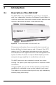
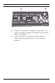
Table Of Contents
- 1 Important Information
- 2 Safety Instructions
- 3 Introduction
- 4 Technical Data
- 5 Installing
- 5.1 Mounting
- 5.2 Unmounting
- 5.3 Opening the Case
- 5.4 Closing the Case
- 5.5 Cabling
- 5.6 Grounding and Shielding
- 5.7 Connecting Power Supply
- 5.8 Ethernet Interface
- 5.9 RS-485 Host Interface
- 5.10 RS-232 Host Interface
- 5.11 DIL switch selector
- 5.12 RS-485 for extension modules
- 5.13 Wiegand Interface for Card Readers
- 5.14 Connecting Relay Outputs
- 5.15 Connecting Analog Input Devices
- 5.16 Tamper Protection
- 6 Operating
- 7 Appendix

20 en | Technical Data AMC2 4W
| V 7.6 | 2008.12 Installation manual Bosch Sicherheitssysteme GmbH
4 Technical Data
Hardware
– Integrated Microcontroller (32 bit, 30 MHz)
–SRAM (256kB)
–Serial EEPROM
–RTC (real time clock)
– Pluggable Compact Flash from 64 MB up to 1 GB
– Battery for SRAM and RTC
– DIL switch for host settings (address and protocol mode)
– Host interfaces
– Ethernet 10/100 Mbit/s
– RS-485 2-wire or 4-wire
Transfer rate: 38,4 kBit/s
(even parity, 7 bit, 1 stop bit)
– RS-232
Transfer rate: 38,4 kBit/s
(no parity, 8 bit, 1 stop bit)
– Four Wiegand interfaces for up to four card readers
(Output rating: 280 mA)
–Eight relay outputs
– maximum ratings:
switching voltage: 30 Vdc
switching current: 1,25 A
– operating ratings:
1,25 A @ 30 Vdc
2 A @ 12 Vdc
1,5 A @ 24 Vdc
– Eight analog inputs with sabotage monitoring; only
connect dry contacts
– RS-485 extension interface:
Transfer rate: 9,6 kBit/s
(no parity, 8 bit, 2 stop bit)
– Tamper contact for enclosures
Power supply