
Installation Manual

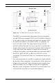
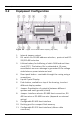
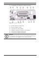
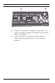
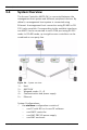
Table Of Contents
- 1 Important Information
- 2 Safety Instructions
- 3 Introduction
- 4 Technical Data
- 5 Installing
- 5.1 Mounting
- 5.2 Unmounting
- 5.3 Opening the Case
- 5.4 Closing the Case
- 5.5 Cabling
- 5.6 Grounding and Shielding
- 5.7 Connecting Power Supply
- 5.8 Ethernet Interface
- 5.9 RS-485 Host Interface
- 5.10 RS-232 Host Interface
- 5.11 DIL switch selector
- 5.12 RS-485 for extension modules
- 5.13 Wiegand Interface for Card Readers
- 5.14 Connecting Relay Outputs
- 5.15 Connecting Analog Input Devices
- 5.16 Tamper Protection
- 6 Operating
- 7 Appendix

AMC2 4W Introduction | en 19
Bosch Sicherheitssysteme GmbH Installation manual | V 7.6 | 2008.12
–the maximum configuration consists of
– up to two PC’s with shared BIS software [Access PE =
one PC]
– up to 200 AMC2 controller [Access PE = 64]
– each controller can be extended with any combination
of three AMC2 8I-8O-EXT, AMC2 16I-EXT, or AMC2 16I-
16O-EXT input/output modules [Access PE = one
extension board]
– each AMC2 4W controller can be extended with an
AMC2 4W-EXT extension module
– the necessary number of AMC PBC-60 power supplies
– the necessary number of AMC enclosures
Using an AMC-MUX interface extension on RS485 host
connections it is possible to connect up to eight controllers to a
single COM port. Up to 200 AMCs can be connected using the
ethernet host connection.
Using Wiegand reader interfaces, up to four peripheral devices
can be connected to each AMC2.The interfaces are point-to-
point connections, meaning that only one reader can be
connected to one interface.
The extension interface supports up to three additional I/O
boards (AMC2 8I-8O-EXT, AMC2 16I-EXT, or AMC2 16I-16O-EXT)
and one AMC2 4W-EXT. All extension boards are controlled by
the AMC2 and are freely combinable.