
Installation Manual

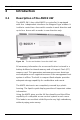
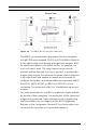
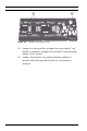
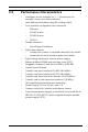
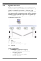
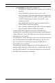
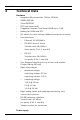
Table Of Contents
- 1 Important Information
- 2 Safety Instructions
- 3 Introduction
- 4 Technical Data
- 5 Installing
- 5.1 Mounting
- 5.2 Unmounting
- 5.3 Opening the Case
- 5.4 Closing the Case
- 5.5 Cabling
- 5.6 Grounding and Shielding
- 5.7 Connecting Power Supply
- 5.8 Ethernet Interface
- 5.9 RS-485 Host Interface
- 5.10 RS-232 Host Interface
- 5.11 DIL switch selector
- 5.12 RS-485 for extension modules
- 5.13 Wiegand Interface for Card Readers
- 5.14 Connecting Relay Outputs
- 5.15 Connecting Analog Input Devices
- 5.16 Tamper Protection
- 6 Operating
- 7 Appendix

18 en | Introduction AMC2 4W
| V 7.6 | 2008.12 Installation manual Bosch Sicherheitssysteme GmbH
3.4 System Overview
The Access Controller AMC2 4W is connected between the
management host system and different peripheral devices. By
default, a management host system is connected using
Ethernet. A management host connection using RS-485 or RS-
232 is also possible. Corresponding to the available interfaces,
one AMC2 can be connected to each COM port using RS-232
mode. In RS-485 mode, up to eight access controllers can be
combined on one party line.
Figure 3.6 System overview
System Configurations:
–the minimum configuration consists of
– one PC with BIS or Access PE software
– one AMC2 controller
– one AMC PBC-60 power supply
– one AMC enclosure
1 = Host
2 = AMC2 4W
3 = Wiegand reader (1 - 4)
4 = Communication and power supply
5 = Ethernet