
Installation Manual

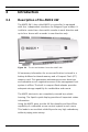
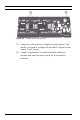
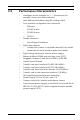
Table Of Contents
- 1 Important Information
- 2 Safety Instructions
- 3 Introduction
- 4 Technical Data
- 5 Installing
- 5.1 Mounting
- 5.2 Unmounting
- 5.3 Opening the Case
- 5.4 Closing the Case
- 5.5 Cabling
- 5.6 Grounding and Shielding
- 5.7 Connecting Power Supply
- 5.8 Ethernet Interface
- 5.9 RS-485 Host Interface
- 5.10 RS-232 Host Interface
- 5.11 DIL switch selector
- 5.12 RS-485 for extension modules
- 5.13 Wiegand Interface for Card Readers
- 5.14 Connecting Relay Outputs
- 5.15 Connecting Analog Input Devices
- 5.16 Tamper Protection
- 6 Operating
- 7 Appendix

AMC2 4W Introduction | en 17
Bosch Sicherheitssysteme GmbH Installation manual | V 7.6 | 2008.12
3.3 Performance Characteristics
– Intelligent access manager for 1 ... 4 entrances (for
example, doors, man traps, barriers)
– Host address selectable using DIL sliding switch
– Four possible configurable host interfaces:
– Ethernet
– RS-485 2-wire
– RS-485 4-wire
– RS-232
– Reader interfaces
– four Wiegand interfaces
–Eight relay outputs
– voltage free, power is supplied externally (dry mode)
– powered by internal power supply (wet mode)
– Eight analog inputs with internal power supply
– Battery buffered SRAM and real time clock (RTC)
– Pluggable Compact Flash from 64 MB to 1024 MB
– Liquid Crystal Display
– Transfer rate host interface RS-485: 38,4 kBit/s
– Transfer rate host interface RS-232: 38,4 kBit/s
– Transfer rate host interface Ethernet: 10/100 Mbit/s
– Transfer rate to the extension interface: 9,6 kBit/s
– Self regulating transmit/receive switching
– Power supply: 10 V to 30 Vdc, max. 5 A
– Tamper contact for internal and external covers
– If an external power supply is used then this should be an
PBC-60 (F.01U.026.573) with integrated uninterruptable
power supply (UPS).